Posted on Leave a comment

Raspberry Pi – NodeRED Button

This simple experiment will demonstrate using a push button to light a LED.
Adding a Push-Button to an LED in Raspberry Pi doesn’t get much easier than with NodeRED, two nodes, and you are done.

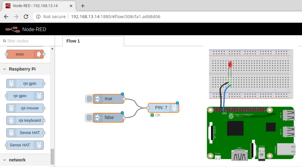
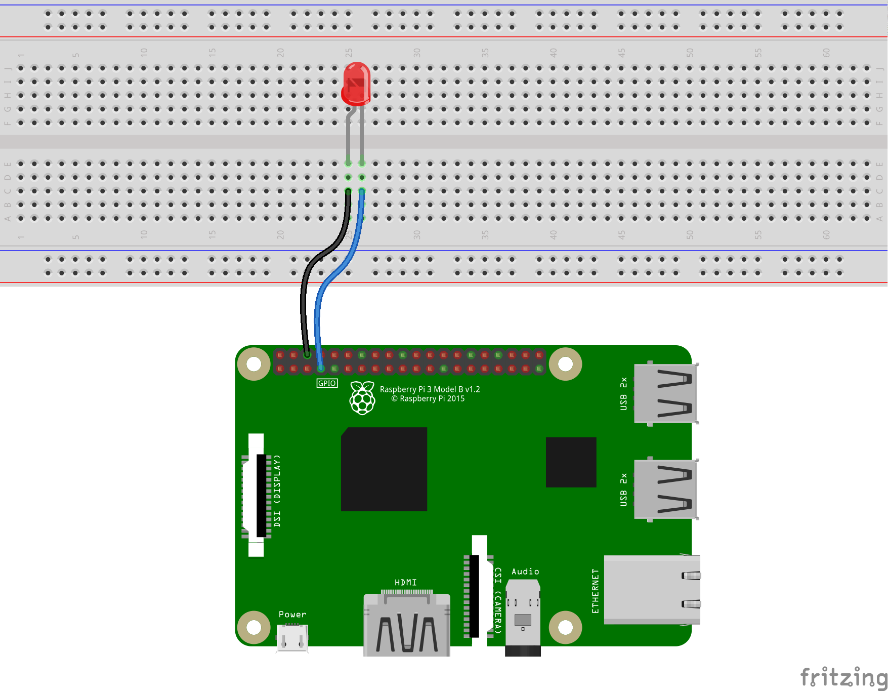
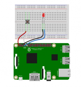
The Fritzing Diagram is availble for download

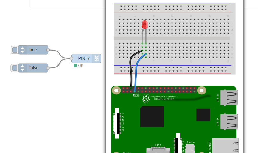
Wire the LED and Button as shown in the Diagram

  • Pin 1 – Left side of button
  • Pin 11 – Right side of button
  • Pin 6 – Led Cathode ( Short Wire / Flat Side )
  • Pin 7 – Led Anode ( Long Wire )

If you simply want to try this Flow, you can import this:

[{"id":"60410dd4.757164","type":"rpi-gpio out","z":"308cfa1.ad68d06","name":"","pin":"7","set":true,"level":"0","freq":"","out":"out","x":253.4615135192871,"y":348.46156311035156,"wires":[]}]

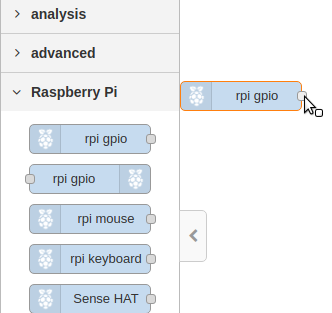
To run this experiment we will use only two nodes rpi-gpio In and rpi-gpio out. Drag one of each onto the Flow edit pane.
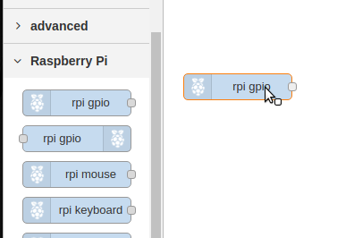
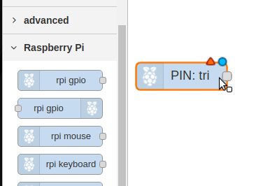
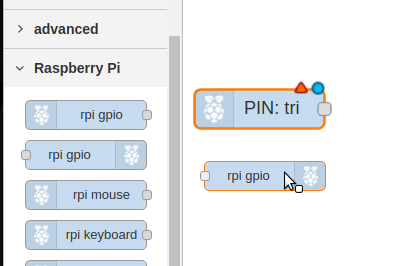
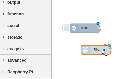
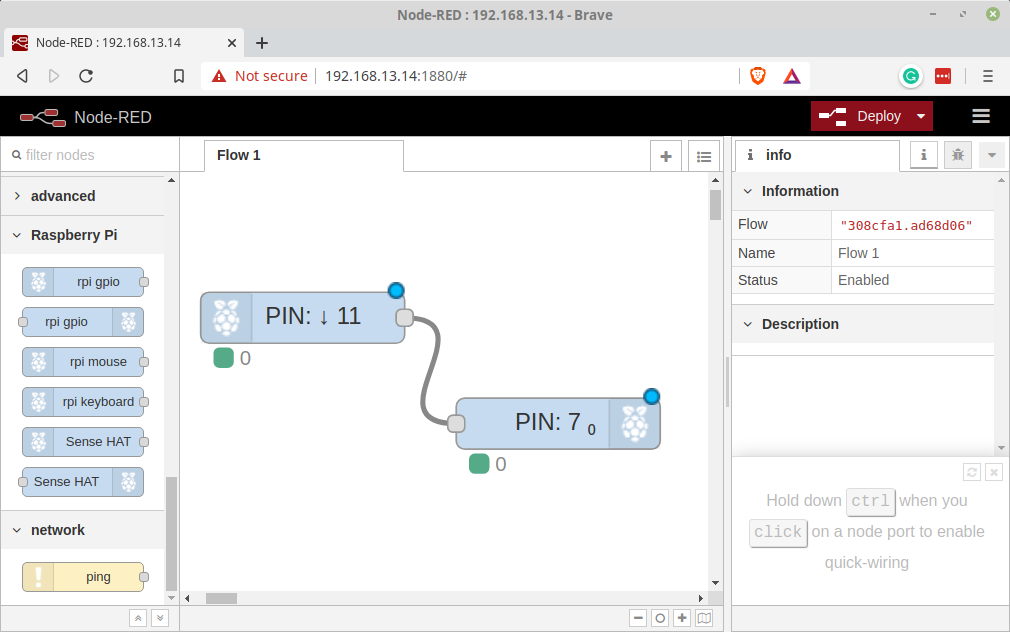
When you drop the Nodes the Labeling is updated to reflect the configuration. The two Nodes before wiring will look like this. There has been nothing done to them other than dropping them onto the flow.
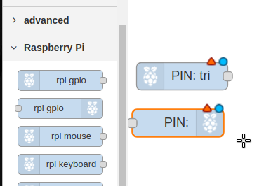
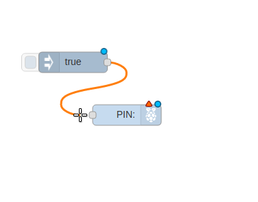
Wire the Nodes together
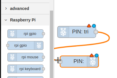
Configure the Input Node

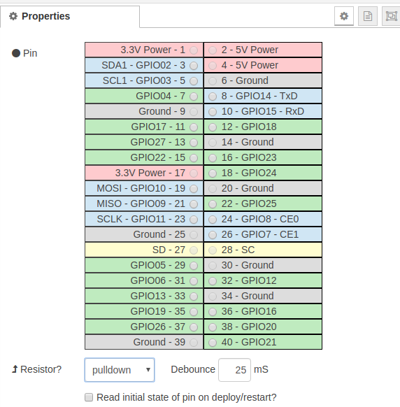
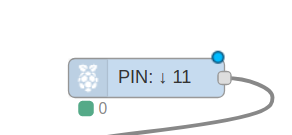
  1. Double Click the rpi-gio In ( it is marked PIN:tri ).
  2. Set the Pin to 11
  3. set the resistor to pull-down
  4. Click Done

The node Should change to PIN 11
Configure the Output Node

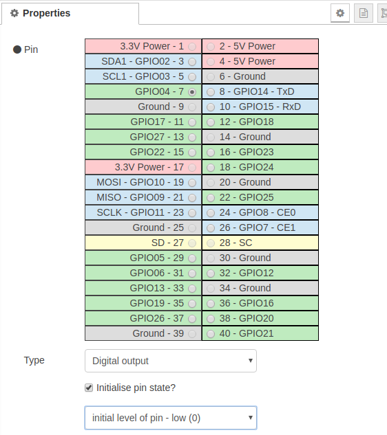
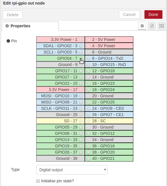
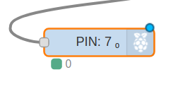
  1. Double Click the rpi-gio out ( it is marked PIN: ).
  2. Set the Pin to 7
  3. Check “Initial pin state?”
  4. Select “initial level of pin -low(0)
  5. Click Done

The Output Node should now be labelled PIN: 7
Deploy the Flow

If you have done everything correctly you should now be able to press the button and the LED will light.

Posted on Leave a comment

Raspberry Pi – NodeRed LED Blink

Using NodeRED to program your RaspberryPi for GPIO Control.

The basic installation of Raspian includes NodeRED. However you need to start it to use it.

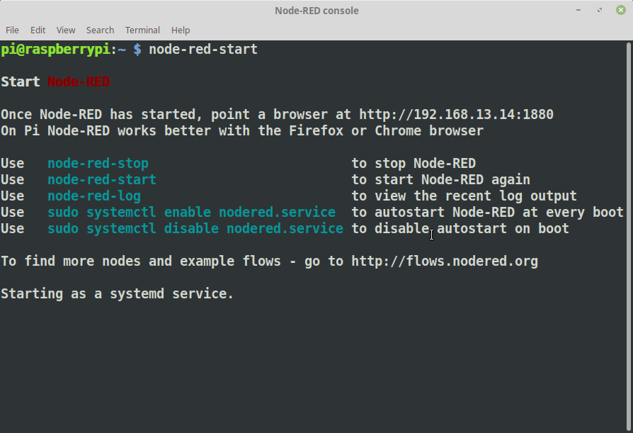
Connect to your Raspberry Pi using your terminal. Issue the NodeRED startup command:
node-red-start

The first line after the “Start Node-RED” will contain where you need to point your browser. Remember that your Raspberry Pi is a fairly small computer so it might take it a little while to load ( possible minutes ).

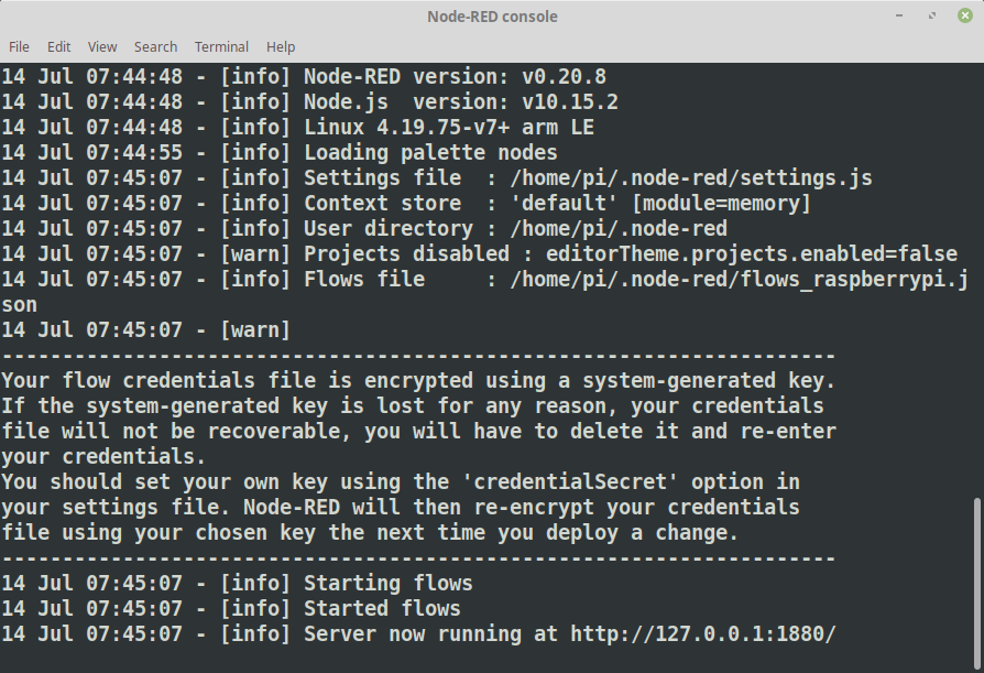
The console will update once Node-RED has started, it is ready when you see the final line state “Server s now Running …”

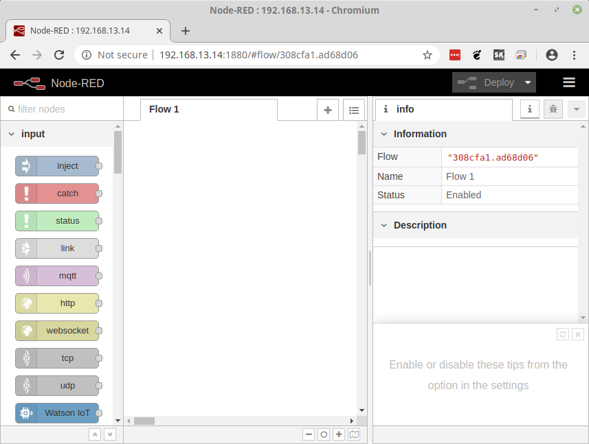
Now we can connect with our browser

Let’s Add Nodes

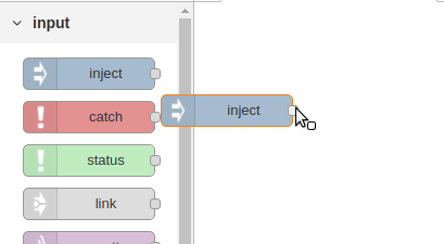
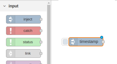
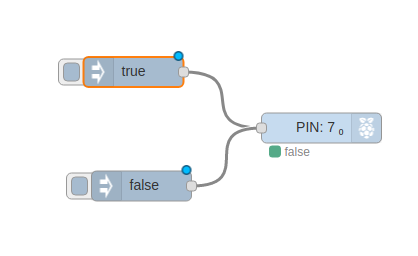
We will use the Inject Node as the “Button”, Drag one of the Inject nodes to the Flow area:

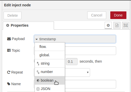
Double click the node to open the edit panel. From the Payload drop-down select boolean and leave the value as True.

Click Done, and you will see that the Inject node now reads as “true”

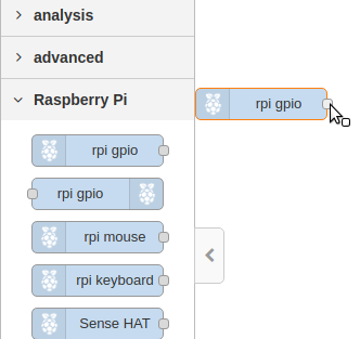
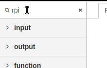
To easily find the Raspberry Pi nodes type rpi in the node search tool at the top left. Drag a single rpi gio Output node to the Flow area and drop it near the Inject Node.

Wire the Inject node to the gpio node:

Double click the PIN Node ( rpi gpio ) to enter into edit mode and select Pin 7 and make certain the type is Digital Output.

Add the “Off Switch”

Let’s Drag a Second Inject node onto the Flow area

Double click the Inject to edit

Change it to boolean and set the value to false.

Wire the “false” node to the same pin as the true node.

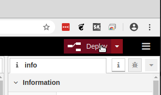
The final step before you can use either of the buttons is to Deploy the Flow.

Clicking the small blue box next to the “true” inject node will turn the LED on and “false” will turn it off.

Posted on Leave a comment

Raspberry Pi – Getting Started with an LED

To get started with controlling and interfacing electronics with the Raspberry Pi, the easiest and safest way is turning a LED On and Off. It is simple but it works.

Interactively, First

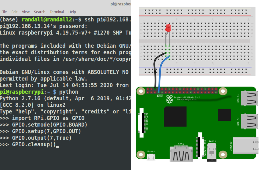
If you have installed Raspian on your Raspberry Pi it comes with Python pre-installed. All you need to do is bring up a terminal and type python <enter> to get to the python console. It looks like this:

The python console let’s you execute code as you go, it is a great way to learn and test small pieces of code.

To control the GPIO pins on the Raspberry Pi we need to add a tool that knows how to control them this is the GPIO Library ( there are others as well ). To add the library we will use the import command. Type the command as show and hit the Enter Key. If done correctly the python console will simply accept it and prompt you for the next line.

>>>import RPi.GPIO as GPIO
>>>

Know that we have the tool we need to tell the python console specifically how to use it. We will be using BOARD mode. This means we will be referring to the PINS as they are physically numbered and laid out. Again you will get no prompt, simply the next line.

>>>import RPi.GPIO as GPIO
>>>GPIO.setmode(GPIO.BOARD)
>>>

The pins are numbered with Odd Pins in one Row and Even pins in the other. The numbering starts from 1 and 2 next to the Power LED. Pin 1 sits near the inside of the board and Pin 2 near the edge. We will wire Pin 6 and Pin 7 to the LED. Pin 6 is GND ( Ground or Negative ) will be wired to the short leg of the LED or the Cathode. Pin 7 will be wired to the Short leg or the Anode.

Next we need to tell python what to do with pin 7. We use the GPIO.setup() command to indicate that the the Pin will be used for output. The GPIO.OUT is used to indicate output.

>>>GPIO.setup(7,GPIO.OUT)
>>>

To turn the LED on we set the pin to True using GPIO.output()

>>>GPIO.output(7,True)
>>>

To turn the LED off we set the pin to False using GPIO.output()

>>>GPIO.output(7,False)
>>>

Let’s make a command file.

To complete this on the command line we will use a program called nano. It is a command line based text editor. For more advance python it can be beneficial to use an IDE

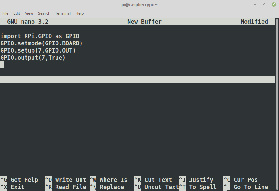
Open the editor by executing the nano command and type all the commands from above into the nano windows

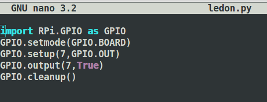
When done press CTRL-O, type in the name ledon.py, press enter the CTRL-X

Test the command, type:

python ledon.py

Our Second Command

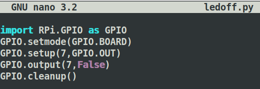
copy the ledon.py to ledoff.py, and open the file with nano ledoff.py

Change the True in line 4 to False

Run the command to turn the led off

python ledoff.py

You will notice there is a warning, let’s take care of that.

Using nano add GPIO.cleanup() to the end of each file

You can now turn the LED On and Off from anywhere you can get a terminal on your Raspberry Pi

Posted on Leave a comment

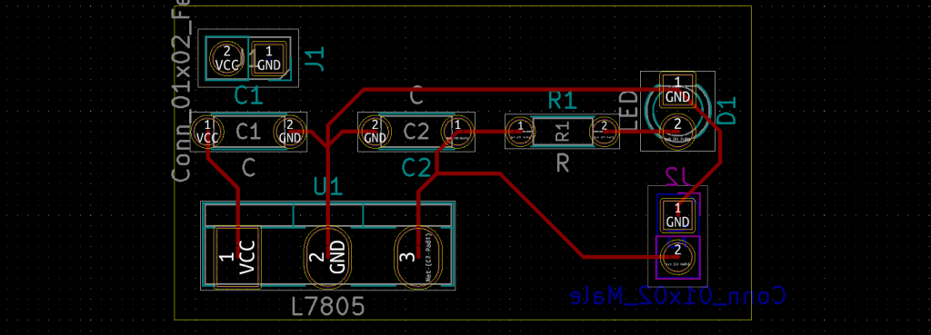
Basic 7805 – KiCAD Beginner – PCB

After we have created a Schematic, Annotated and assigned Footprints we can create a PCB and bring in components from the schematic.

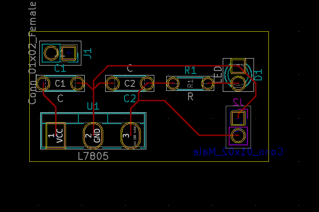
Come Back Soon! This is in progress. Should be done by Friday July 10th. If you just can’t wait you might be able to muddle through with the diagram below. I still need to hookup J1 tho.

Get the Symbols from Schematic

The first thing we will need to do is “import” the components, using the symbols from the schematic. This process will use the Footprints we assigned previously to place the Components base on the Symbols we selected in the Schematic. ( You might want to read that a few times.)

Continue reading Basic 7805 – KiCAD Beginner – PCB
Posted on Leave a comment

Basic 7805 – KiCAD Beginner – Schematic

From to Design to Circuit Board.

This Tutorial will cover the use of KiCAD to create a Schematic, PCB and send that PCB to a Manufacturer. It is not a tutorial in the underlying electronics or electronic theory. Use of circuits in this tutorial are at your own risk and should be limited to educational purposes only.

Creating the Schematic

The first step in getting a circuit board ready to be manufactured is to create a schematic. This Step-By-Step how-to will walk through the creation of a very basic implementation of the L7805 5v Power Regulator.

Continue reading Basic 7805 – KiCAD Beginner – Schematic
Posted on Leave a comment

Arduino – Control a Servo

Materials

  • Arduino Uno
  • Micro-Servo
  • Hookup Wire

Coding

In order to easily code for a Servo motor, it is best to use a library. This example uses the Servo.h library from barraganstudio.com

The code below is from the example, but with the pin changed and the comments removed.

/* Sweep
by BARRAGAN http://barraganstudio.com
This example code is in the public domain.modified 8 Nov 2013
by Scott Fitzgerald
http://www.arduino.cc/en/Tutorial/Sweep
*/
#include <Servo.h>

Servo myservo;

int pos = 0;

void setup() {
  myservo.attach(10);
}

void loop() {
  for (pos = 0; pos <= 180; pos += 1) { 
    myservo.write(pos);  
    delay(15); 
  }
  for (pos = 180; pos >= 0; pos -= 1) {
    myservo.write(pos); 
    delay(15);
  }
}

Wiring

The wiring for this example is very simple

  1. Connect +5v on the Arduino UNO to the Red wire on the Servo ( or +5v / Vcc if marked )
  2. Connect GND on the Arduino UNO to the Black wire on the Servo ( or GND if marked )
  3. Connect Pin 10 on the Arduino UNO to the remaining wire on the Servo

Posted on Leave a comment

Cura – Slicing Software

Cura is a very popular and easy to use slicing software. It is an Open Source software made by Ultimaker. The novice 3d Printing enthusiast will generally find Cura simple enough to get started but powerful enough to use for a long time. Cura removes some of the chores of preparing G-Code by automatically performing tasks like “center” and “lay flat”.

A downside to CURA is that is increasingly moving away from Home-brew printers and relying on manufacturer printer definitions. This author is moving away form CURA for that reason.

Some of the newer more interesting features is the material handling. With material definitions getting it’s own management CURA has begun the abstraction of material specific settings away from machine settings. This is probably a good thing.