
From to Design to Circuit Board.
This Tutorial will cover the use of KiCAD to create a Schematic, PCB and send that PCB to a Manufacturer. It is not a tutorial in the underlying electronics or electronic theory. Use of circuits in this tutorial are at your own risk and should be limited to educational purposes only.
Creating the Schematic
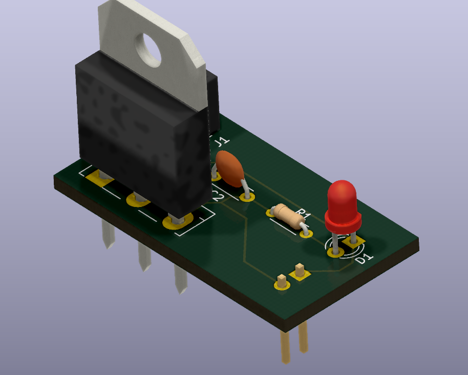
The first step in getting a circuit board ready to be manufactured is to create a schematic. This Step-By-Step how-to will walk through the creation of a very basic implementation of the L7805 5v Power Regulator.
Start by creating a new project.
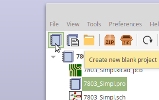
When you first open KiCAD you are presented with the “Project Manager” window. This Window will contain the multiple pieces used to manufacture the PCB. Start out by clicking the Create a new blank project. It is the Light Blue notebook icon, in the upper left corner.
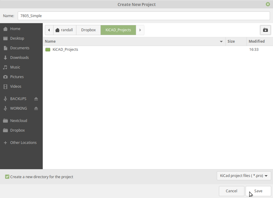
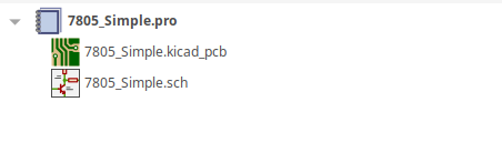
Choose the folder where you would like you project to stored, type 7805_Simple in the name and click Save.
You project is created and we can work on the Schematic.
Click on the Schematic Icon in the project tree or above the message window.
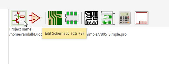
You will be taken to the Schematic window and we can begin. We will start be adding the 7805 “Symbol”.
Note: Symbols represent electronic parts on the Schematic, while Components represent electronic parts on the Printed Circuit Diagram. This is an important consideration. ( we will repeat this often ).
Click on the Symbol Icon on the right side of the Screen, or, from the menu select “Place -> Symbol”
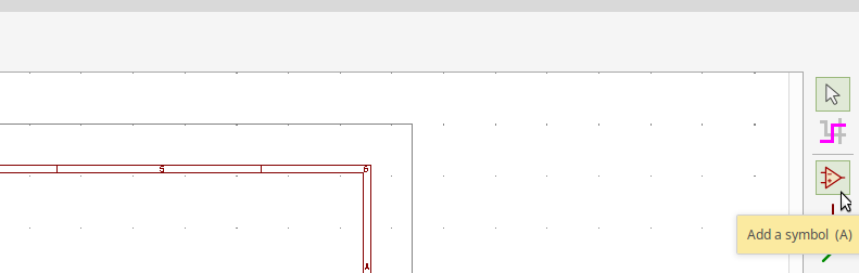
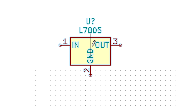
The cursor will change to a cross-hair click somewhere in the middle of the screen. The Symbol library will load for a few moments and you will be given the chance to select a symbol. Type 7805 in the search field, then highlight the L7805.
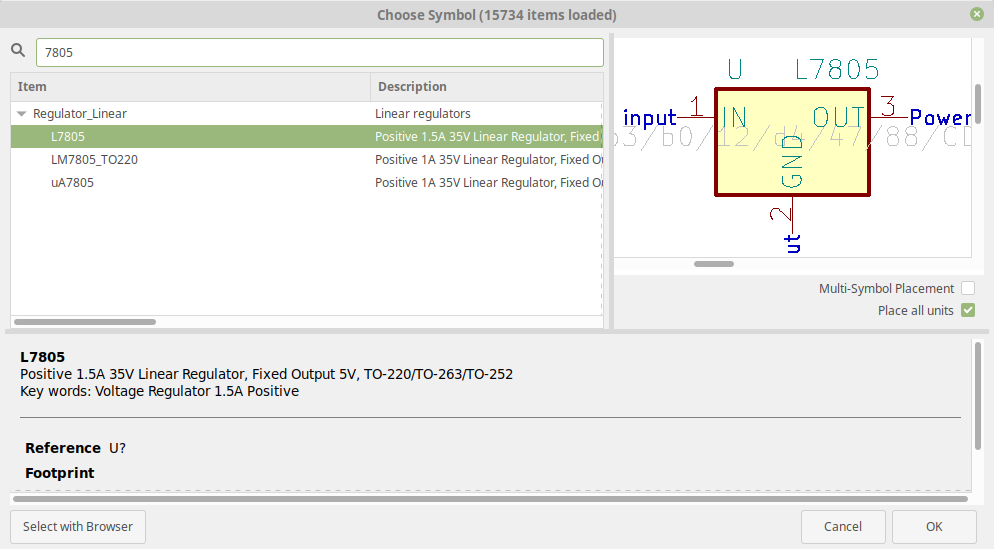
When you have the regulator selected click OK. You will see the component you just selected attached to the a pencil. Pick a spot to drop this and click your left mouse.
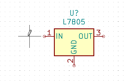
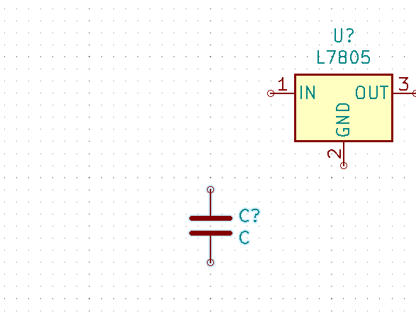
Next we will add two capacitors. Your cursor should still be the crossed lines for Symbol Placemnet, click on the white area near the 1 Pin on the 7805
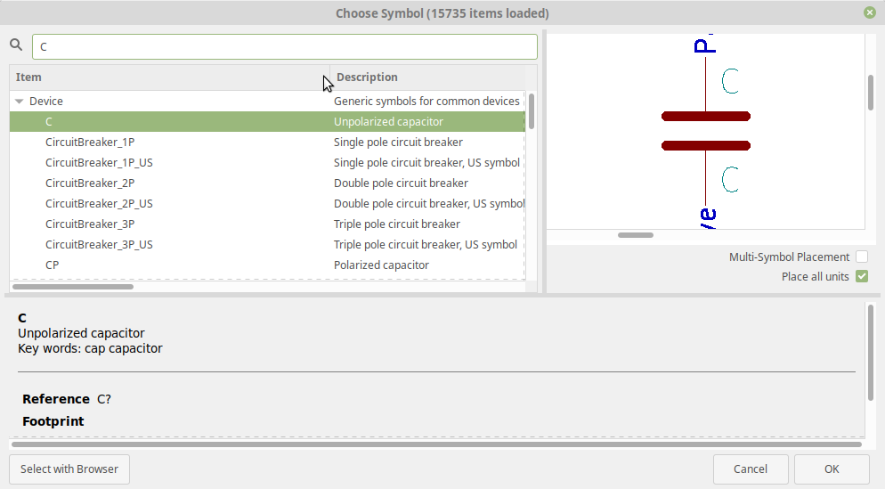
When presented with the Symbol browser type “C”, in the search box, and click OK to begin Placement.
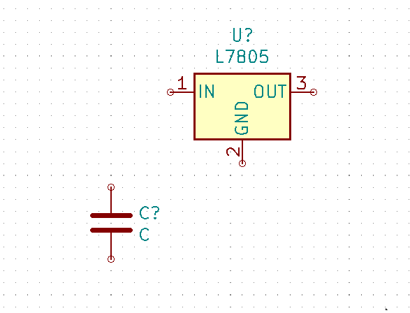
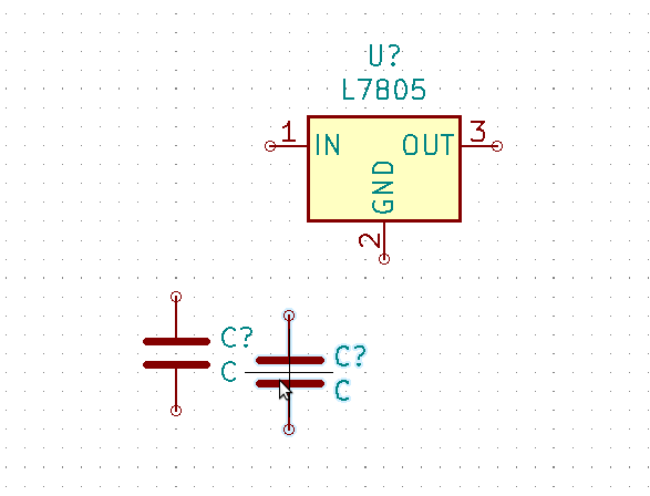
You should now have a Symbol as below, click the symbol once to highlight it ( it will glow slightly blue ), and press Ctrl-D to Duplicate, this is our second Capacitor
We need to add the following Symbols:
- Resistor
- LED
- Connector Male
- Connector Female
The Procedure as we learned above is :
- Click on location
- Search for Symbol
- Click OK ( or press return )
- Place Symbol
Use these terms to search:
- R – Use the generic resitor, It is named R with the descirption of Resistor
- LED – Use the Generic LED, It is named LED with the description of Light emitting Diode.
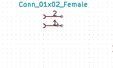
- conn – For the Connectors, select Conn_01x02_Female and Conn_01x02_Male, symbols
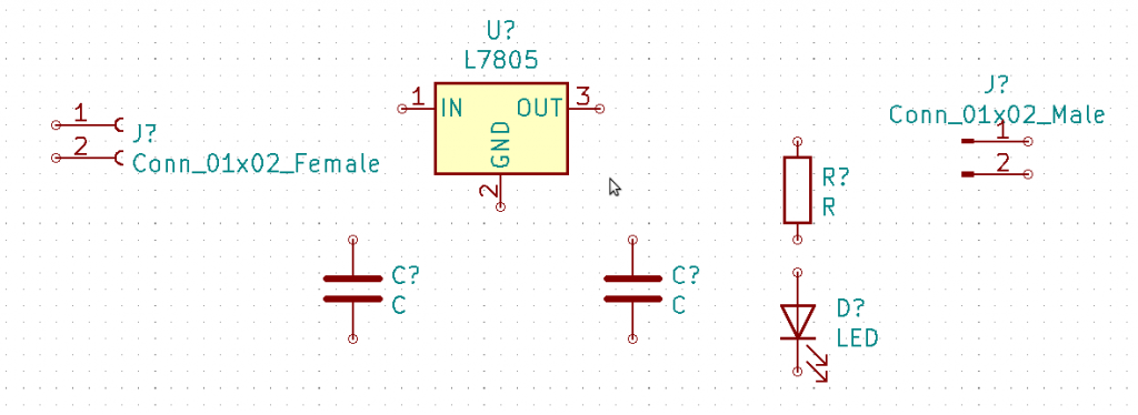
Moving Symbols
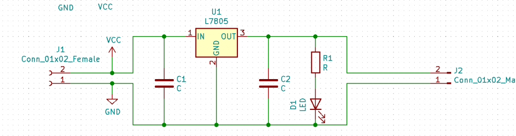
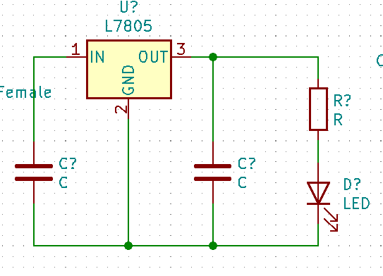
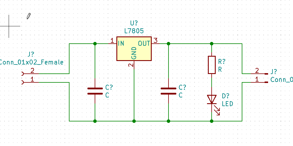
We will need to move things around so the Schematic will look reasonable. Use this diagram as a guide and the “Moving Symbols” section below
To move a Symbol use the following Steps
- Click the Symbol
- Press M ( for Move )
- Use your mouse to position the Symbol
- Left Click to Place the Symbol
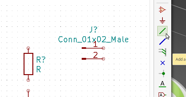
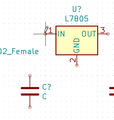
After you have the Symbols position reasonably, click on the “Add a Wire” tool in the right hand toolbar. It is a green slanted wire.
With the crossed lines icons hover over the CIrlce to the left of the IN ( 1) pin of the 7805.
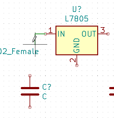
Click on the circle
Drag the mouse to the left and down to the top of the Cpacitor
Click on the circle above the capacitor
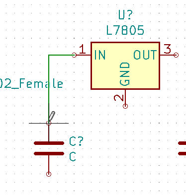
You have now connected your first wire.
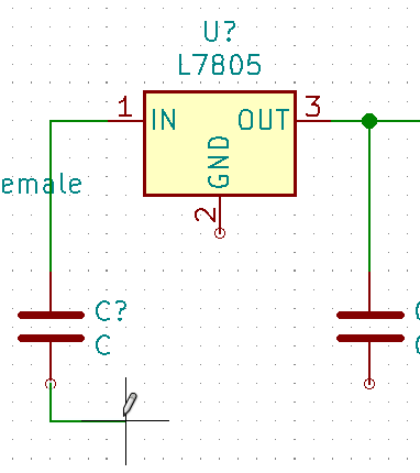
Using the same procedure, make the following connections
- Connect OUT(3) to the second Capacitor
- Connect OUT (3) to the Resistor
- Connect the resistor to the LED
Connecting up Ground
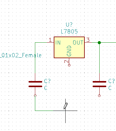
We can start by using the wiring tool to connect GND
Click The bottom wire on the capacitor move down a small amount, click to place a corner, move to the right a small amount, click the mouse to create a second corner, and click the circle by the GND to finish.
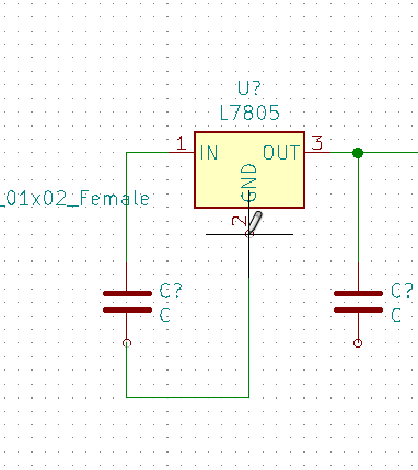
Use the above procedure to connect the second capacitor and the LED to GND
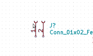
We need to rotate both connectors before we move on. Highlight the connector with a single click and press r, twice to rotate it.
We are almost done ! Use what you have learned to wire the two connectors.
This is all we need to go the PCB, but if you want to use the Electric Rules Checker (ERC) we need to add some Power Flags
Optional, Power Flags
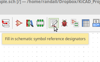
Running Annotation
You will notice that non of our symbols are numbered, the all have ? in the Label, we need to run the Annotation tool to number them
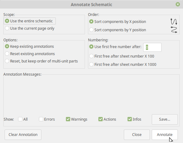
Use the defaults and Click Annotate.
The Schematic portion is finished! Go to the Footprint Article to learn how to add
Footprints to your components.