
This simple experiment will demonstrate using a push button to light a LED.
Adding a Push-Button to an LED in Raspberry Pi doesn’t get much easier than with NodeRED, two nodes, and you are done.
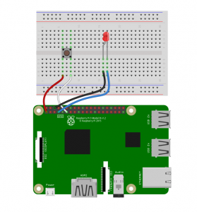
The Fritzing Diagram is availble for download
Wire the LED and Button as shown in the Diagram
- Pin 1 – Left side of button
- Pin 11 – Right side of button
- Pin 6 – Led Cathode ( Short Wire / Flat Side )
- Pin 7 – Led Anode ( Long Wire )
If you simply want to try this Flow, you can import this:
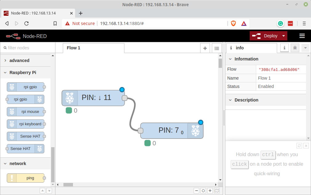
[{"id":"60410dd4.757164","type":"rpi-gpio out","z":"308cfa1.ad68d06","name":"","pin":"7","set":true,"level":"0","freq":"","out":"out","x":253.4615135192871,"y":348.46156311035156,"wires":[]}]To run this experiment we will use only two nodes rpi-gpio In and rpi-gpio out. Drag one of each onto the Flow edit pane.
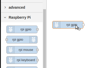
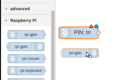
When you drop the Nodes the Labeling is updated to reflect the configuration. The two Nodes before wiring will look like this. There has been nothing done to them other than dropping them onto the flow.
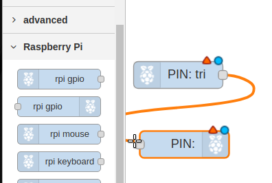
Wire the Nodes together
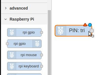
Configure the Input Node
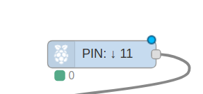
- Double Click the rpi-gio In ( it is marked PIN:tri ).
- Set the Pin to 11
- set the resistor to pull-down
- Click Done
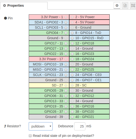
The node Should change to PIN 11
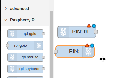
Configure the Output Node
- Double Click the rpi-gio out ( it is marked PIN: ).
- Set the Pin to 7
- Check “Initial pin state?”
- Select “initial level of pin -low(0)
- Click Done
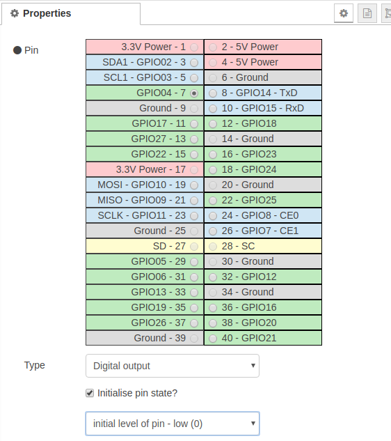
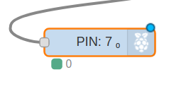
The Output Node should now be labelled PIN: 7
Deploy the Flow
If you have done everything correctly you should now be able to press the button and the LED will light.