
Materials
- Raspberry Pi 3
- 16×2 LCD
- Breadboard
- Hookup Wire
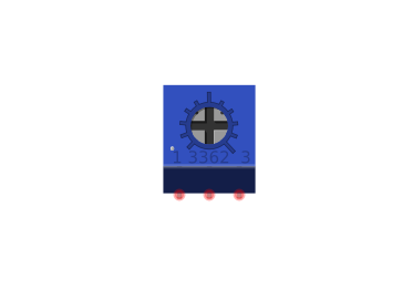
- Trimmer / Potentiometer
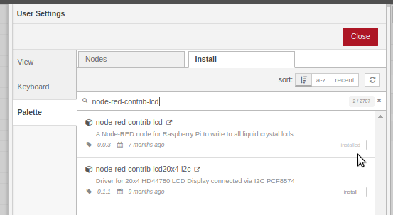
Use the Pallete manager to install node-red-contrib-lcd
https://flows.nodered.org/node/node-red-contrib-lcd
Flows

Add the LCD Node to your flow.
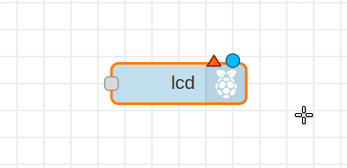
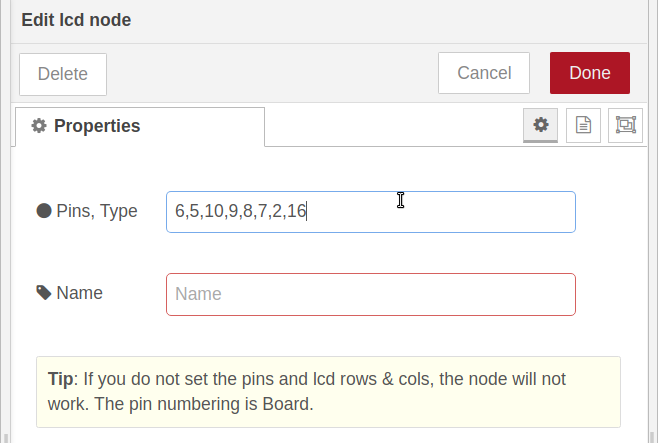
The LCD node requires a string indiacting whcih pins of the LCD are connected to which pins of the pi. The format is shown when you double click the node to configure it.
The “Pins, Type” field will give you the format \: RS, EN, D7, D6, D5, D4, ROW, COL
The pin numbering using Board numbering is 6,5,10,9,8,7,2,16
Add the pin numbering and click done.
Board Numbering: 6,5,10,9,8,7,2,16
GPIO Numbering : 31,29, 26,24,21,19, 2,16
Board numbering is simply sequential with even numbers from 2 on the outer row and odd numbers from 1 on the inner row.
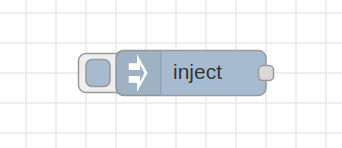
Add an inject node:
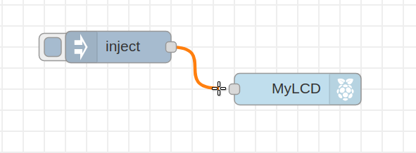
Connect the inject node to the LCD node.
Double click the inject node and add a string to,
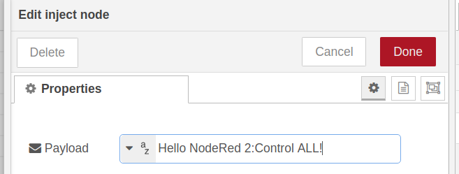
That’s all there is on the NodeRED end, you can deploy now or wait until after wiring.
If you don’t want to wire up the Flow you can just copy in this:
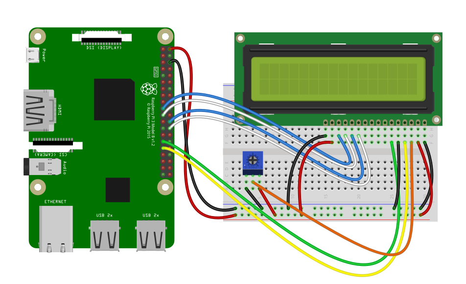
Wiring
The Full Fritzing Diagram is on TeachersPayTeachers.com
Let’s wire up our Pi and LCD as follows. Some color coding can help but the colors are not important.
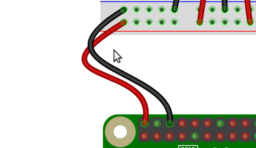
Connect a Wire from “PIN 2” on the RaspberryPI to the Lower rail ( Red ) on your breadboard. This is +5volts and will be used to power the LCD and the LCD Backlight
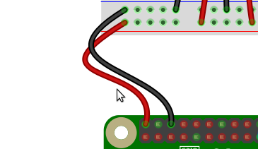
Connect a second wire from PIN 6 to the Blue Rail on the Breadboard, this will provide the GRound or NEG for the LCD.
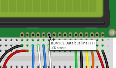
Connect the DATA Lines
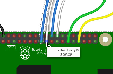
We can connect the four Data lines from the LCD to any GPIO Pins on the RaspberryPi. In this example, GPIO 7,8,9,10 were selected for visual location and consecutive numbering. As shown we will be using Blue and White wires for the DATA lines but any color can be used.
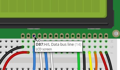
Connect GPIO10 to the Breadboard directly below the LCD Pin As Shown. It will be the third pin from the left and likely labelled D8, Pin 14 or sometimes DB7.
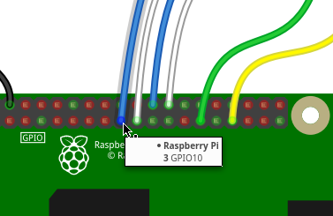
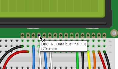
Connect GPIO 9 to D7 ( DB6 )
Connect GPIO 8 to D6 ( DB5 )
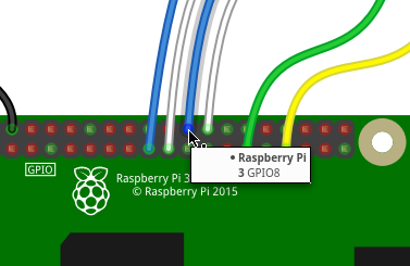
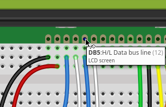
Connect GPIO 7 to D6 ( DB5 )
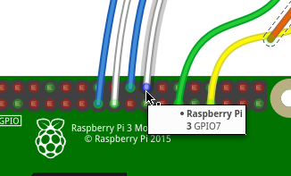
Connect the Control Lines
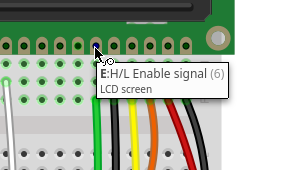
There are only two lines that will be used to control the LCD. Enable and Command Mode. The enable line is basically the on/off switch for the LCD connected to the PI and the Command Mode or “Register Select” informs the LCD if it will be receiving a command to act upon or letters to display.
Connect GPIO5 to the Breadboard colum directly beneath the E pin on the LCD.
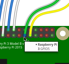
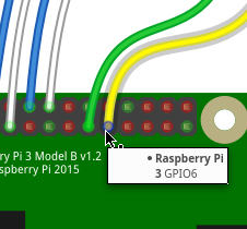
Connect GPIO6 to the Breadboard colum directly beneath the RS Pin on the LCD

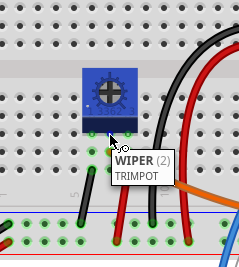
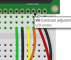
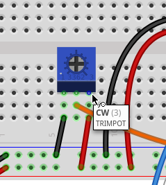
Wire the Contrast Knob
Trimmer/PotentiometerPotentiometer ) to the LCD VO ( Contrast ). Make sure you coonect the “Wiper” the cneter in this case to the column directly beneath the VO
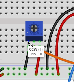
Connect the Dimmer s( Trimmer/Potentiometer ) legs CW and CCW to +5v and Ground, the polarity of these two determine whether the contrast is increased with a Clockwise turn or a Counter-Clockwise turn.
Hello,
and thankx for your work. Unfortunately i got an error:
“Error: Command failed: python2 “/data/home/nodered/.node-red/node_modules/node-red-contrib-lcd/lcd.py” 6,5,10,9,8,7,2,16 Hello#/@$%NodeRed 2:Control ALL!
/bin/sh: python2: command not found”
Can you give me any hints to solve the problem.
For info: I am using a Raspberry Pi, running VictronVenus with node red installed.
Thanks in advance
Peter