
Adding a Display to you project can add a tremendous amount of value and feature. This simple project shows the learner how to hook up the LCD using four wires and 2 for control.
Downloads

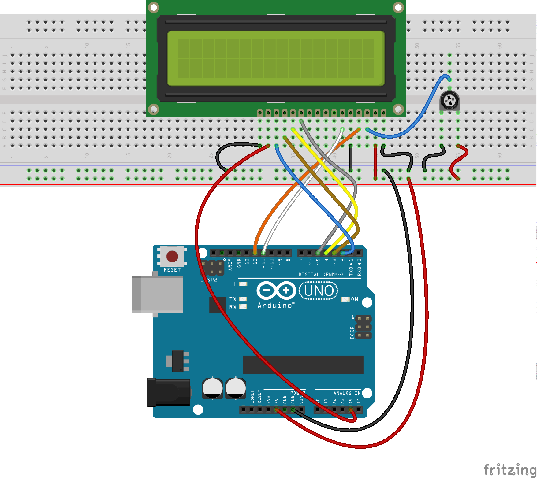
- Wiring Diagram
- Schematic
- PCB
- Arduino Code
If you work with Fritzing you can wire the Arduino and Run the code right from Fritzing.
Arduino Code Files – Our custom commented code with the bare minimum to ease understanding.
f you want to use the Arduino IDE or create.arduino.cc or other coding tool you can download this code.
Arduino Code Files – Version with NO COMMENTS.
f you want to use the Arduino IDE or create.arduino.cc or other coding tool you can download this code.
Video Tutorial
Materials
- Arduino UNO
- 8 x 5mm LEDs
- 1602 LCD
- Hookup Wire
- Jumper Wires
- Breadboard
- Potentiometer
Coding Directions
Using your editor of choice load the mcp_lcd.ino code onto your Arduino
For step by step instructions go here (TBD)
For video instructions go here ( TBD )
Wiring Directions
These directions assume you have aligned the LCD Pin 1 to Column 1 on your Breadboard.
Step 1.) Wire the Four Data Lines
- Connect Pin 2 on the Arduino to Pin 14 on the LCD ( Col 14 ) aka D7
- Connect Pin 3 on the Arduino to Pin 13 on the LCD ( Col 13 ) aka D6
- Connect Pin 4 on the Arduino to Pin 12 on the LCD ( Col 12 ) aka D5
- Connect Pin 5 on the Arduino to Pin 11 on the LCD ( Col 11 )aka D4
Step 2.) Connect Power and Ground
- Connect the 5v Pin from the Arduino Power Header to the Red Power Rail on your Breadboard
- Connect the GND Pin from the Arduino Power Header to the Blue Power Rail on your Breadboard
Step 4.) Connect the Backlight
- Place a jumper wire from the Blue Power rail on your breadboard to Pin 16 on the LCD ( Col 16 on Breadboard ) aka K – This is the ground for the Backlight
- Place a jumper wire from the Analog Pin 4 on your Arduino to Pin 15 on the LCD ( Col 15 on Breadboard ) aka A – This is the power for the Backlight
Step 5.) Set “defaults” by Grounding and Powering Pins
- Jumper LCD Pin 1 ( Breadboard Col 1 ) to the GND rail – This sets the LCD to W(rite)
- Jumper LCD Pin 2 ( Breadboard Col 2 ) to the 5v rail – This powers the LCD
- Jumper LCD Pin 5 ( Breadboard Col 5 ) to the GND rail – This sets the LCD to W(rite)
Step 6.) Connect the Register Select line
- Connect Pin 12 on Arduino to Pin 4 on LCD
Step 7.) Connect the Enable Line
- Connect Pin 11 on the Arduino to Pin 6 on the LCD ( Column 6 on Breadboard )
Step 8.) Wire the Contrast Control.
- Place the 3 Pin Potentiometer in Columns 20,21,22
- Connect Column 20 to the 5v Rail
- Connect Column 22 t the Blue Ground Rail
- Jumper Column 21 to Pin 3 on the LCD ( Column 3 on Breadboard )
Additional Materials
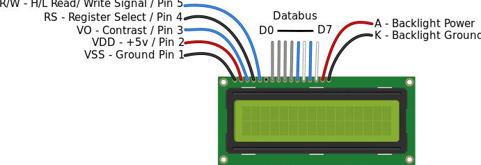
LCD Pin Diagram
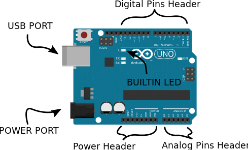
Arduino Diagram
Absolutely amazed by this Arduino project! The creativity and technical skill showcased here are truly impressive. Thanks for sharing this incredible work!