Posted on Leave a comment

Getting Started: Installing Node-RED on Raspberry Pi

Introduction: Node-RED is a popular flow-based programming tool that allows users to create powerful and interactive applications by wiring together different nodes. Raspberry Pi, with its GPIO pins and Linux-based operating system, provides an excellent platform for running Node-RED. In this article, we will guide you through the process of installing Node-RED on your Raspberry Pi, enabling you to unleash the full potential of this versatile tool.

Step 1: Preparing your Raspberry Pi:

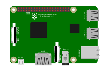
  1. Connect your Raspberry Pi to a monitor, keyboard, and mouse.
  2. Ensure that your Raspberry Pi is connected to the internet.

Step 2: Updating the System:

  1. Open a terminal window on your Raspberry Pi.
  2. Update the package lists by running the following command:
sudo apt update
  1. Upgrade the installed packages to their latest versions with the command:
sudo apt upgrade

Step 3: Installing Node.js:

  1. Install Node.js on your Raspberry Pi by executing the following commands:
sudo apt install nodejs

Step 4: Installing Node-RED:

  1. With Node.js successfully installed, proceed to install Node-RED by running the following command:
sudo npm install -g --unsafe-perm node-red

Step 5: Launching Node-RED:

  1. Start Node-RED by entering the command:
node-red

Step 6: Accessing the Node-RED Editor:

  1. Open a web browser on your Raspberry Pi and navigate to http://localhost:1880.
  2. You will be greeted with the Node-RED editor interface.

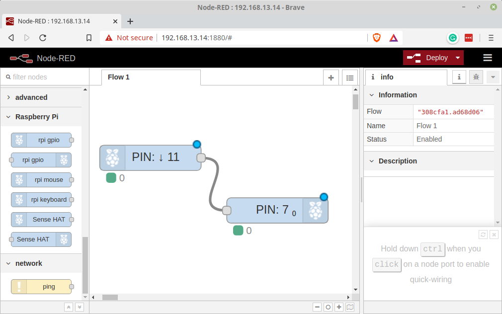
Step 7: Exploring the Node-RED Editor:

  1. Spend some time familiarizing yourself with the Node-RED editor’s layout and functionality.
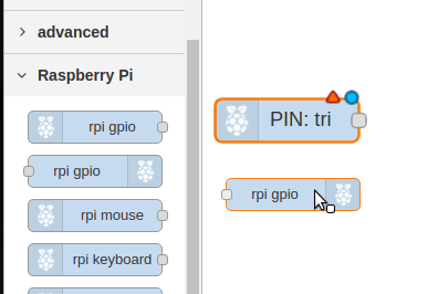
  2. On the left side, you will find a palette of nodes that can be used to build your flows.
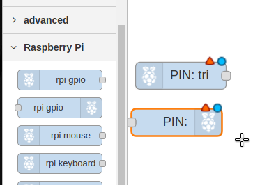
  3. In the center, you can drag and drop nodes onto the canvas and connect them together to create flows.
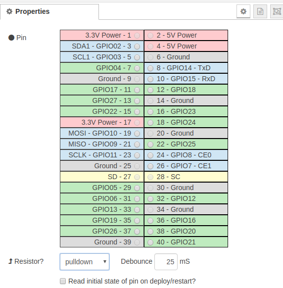
  4. The right side contains additional information, debug panels, and configuration options.

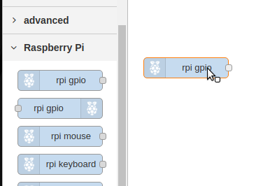
Step 8: Building your First Flow:

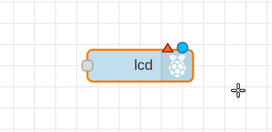
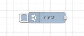
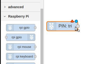
  1. Start by dragging a node from the palette onto the canvas.
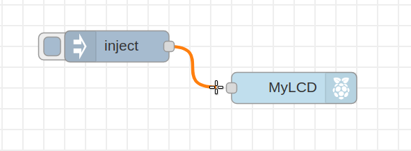
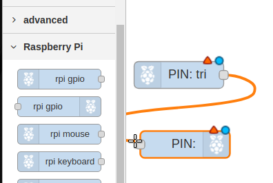
  2. Connect the output of one node to the input of another by clicking and dragging from one node’s output to another node’s input.
  3. Experiment with different nodes and connectors to create a simple flow.

Step 8: Building your First Flow (contd.):

  1. Click the “Deploy” button in the top-right corner of the Node-RED editor to activate your flow.

Step 9: Exploring Additional Nodes and Flows:

  1. Node-RED provides a vast library of additional nodes that can extend the functionality of your applications.
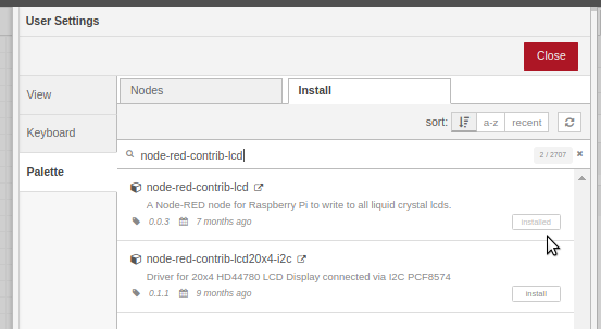
  2. Click on the “Manage Palette” option in the main menu to access the Node-RED library.
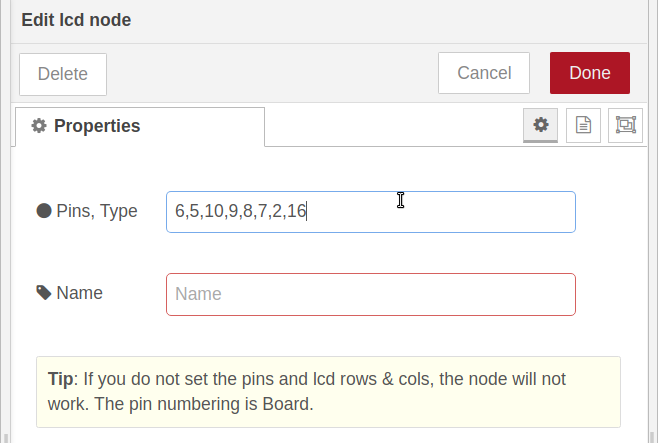
  3. Explore the available nodes, install the ones you need, and incorporate them into your flows.

Step 10: Automating Node-RED Startup (Optional):

  1. If you want Node-RED to start automatically when your Raspberry Pi boots up, you can use the systemd service manager.
  2. Execute the following commands to create a service for Node-RED:
sudo systemctl enable nodered.service
sudo systemctl start nodered.service

Conclusion: By following the step-by-step instructions in this article, you have successfully installed Node-RED on your Raspberry Pi. You are now equipped to explore the powerful features and capabilities of Node-RED’s visual programming environment. Use the Node-RED editor to create flows, connect nodes, and build interactive applications for your Raspberry Pi. Enjoy the creative possibilities that Node-RED offers and have fun experimenting with different nodes and flows!

Posted on Leave a comment

Keyboard and Mouse Sharing – Linux + Pi

Bare Bones Install Instructions ( It just worked. ) The bare minimum to get a working installation of the Keyboard+Mouse sharing software Barrier. This can also be used from a Windows machine to a Linux machine or Raspberry Pi.

Barrier – A simple Open Source tool that enables sharing a Keyboard and mouse acrros muliple screens.

Linux Mint 19.x – Install

sudo apt update

sudo apt install snapd

sudo snap install barrier

Raspberry Pi – Install

sudo apt update

sudo apt install barier

Linux Mint 19.x – Run

barrier

Raspberry Pi – Run

barrier

Configure “Server”

In this installation the Server is the Linux 19.x machine. The machine with the Keyboard physically attached is the server. Place the screen in the correct position ( Each screen represents the whole PC, not the actual screen count .) The name of the machine must match the hostname on the raspberry pi. This will be shown in “Screen name:” of the client”

Once you have finished configuring the server, click the Apply button an then the Start button. The start button will change to a “Stop” button and the screen will show “Barrier is running” in the bottom left corner.

Configure Client

You will need the IP Address of the Server from the Server’s Main Screen. Uncheck “Auto Config” enter the IP address. Re-Check Autoconfig. As before press Apply and Stop. The client will connect and you will be able to move your mouse across both screens. ( Try re-starting server-side if it doesn’t work )

NOTES:

  • Your mouse point must be on the screen to which you are typing.
  • If the client dis-connects first try restarting the server.
Posted on Leave a comment

Rasberry Pi – Python Blink

Make a single LED Blink using Raspberry PI GPIO and Python.

Using the RPi.GPIO library we can program the LED to blink on and off. The GPIO library gives us easy access to the Pins of the Raspberry Pi.

Take a moment to print out this guide, with a custom template to make hookup dead simple.

https://www.teacherspayteachers.com/Product/Raspberry-Pi-Blink-Project-Guide-5959017

Requirements

  • A Raspberry Pi 2/3/4
  • A single LED
  • 2 Hookup Wires
  • A 2.2K Ohm Resistor
  • Prototyping Breadboard
  • A Raspberry Pi with Rasbian Installed and Running
  • Access to the Shell on the Raspberry Pi

First Let’s Wire Up the Pi and the LED

Get Ready

It can be extremely useful to get a PIN template and push it onto the Pins of the PI

I got mine from her : https://www.computerhilfen.de/english/raspberry-pi-gpio-paper-template.html

Raspberry Pi GPIO paper-template

It is a actual sized and designed to pushed on the pins. Inlcuded in this article is a template custom labelled for this project.

Hook-Up Wires

It is easiest to use hookup wire that has one female end and one male end. The female end is easily pushed onto the RaspberryPI pins and the male end is easily inserted into the Breadboard.

1.) Connect One hookup wire from Pin 6 GND on the Raspberry Pi to Column 10 on the Breadboard

2.) Connect One hookup wire from Pin 7 GPIO 4 on the Raspberry Pi to Column 5 on the Breadboard

3. )Place the LED with the Short Lead, the Anode, inserted into Column 10 and the Long Lead, the Cathode into Column 9 on the Breadboard.

Identify LED Parts

  • The Anode of the LED can be identified in three ways.
    • It is the Long LEAD/Wire
    • The Lens will be rounded ( flattened side is cathode )
    • Looking into the led, the Anode is the “Post” the smaller metal bit.
  • The Cathode of the LED can also be identified in three ways.
    • It is the Short Lead/Wire
    • The Lens will have ( usually ) a small flat spot.
    • Inside the Lens the wire connects to the “Anvil” or the larger metal piece.
  1. Place the resistor from Column 9 to Column 6 on the Breadboard. The resistor has no polarity, so it can be connected in either direction.

That’s all it takes to hook up the LED.

The resistor is a used to limit the amount of current that goes through the LED, it protects the LED from ever getting to much current and burning out.

To aide with wiring here is a diagram from Fritzing:

Now Let’s Add Code

Log on to your Pi using the Pi Desktop or using SSH to get to a Terminal.

Place the following code into a file named rpi_blink.py ( or whatever name you like ), you just copy this code into your text editor or open your text editor and type it in.

import RPi.GPIO as GPIO 
from time import sleep
GPIO.setwarnings(False)
GPIO.setmode(GPIO.BOARD)
GPIO.setup(7, GPIO.OUT, initial=GPIO.LOW)


while True: 
    GPIO.output(7, GPIO.HIGH)
    sleep(1)
    GPIO.output(7, GPIO.LOW)
    sleep(1)

Once you svae the code you can execute the project as follows:

python rpi_blink.py

To stop the code from running press

ctrl-c

Additional Activities

Blink Faster or Slower

To make the LED blink faster you can experiment with different values within the Sleep( ) command.

Try changing the value in Sleep to .1, it should look like this

while True:
    GPIO.output(7, GPIO.HIGH)
    sleep(.1)
    GPIO.output(7, GPIO.LOW)
    sleep(.1)

Make sure you change it in both locations/

Blink at different rates

To make the LED stay on for a different amount of time than it stays off change the values in sleep to differnent values.

A quick blink, can look like this:

while True:
    GPIO.output(7, GPIO.HIGH)
    sleep(.1)
    GPIO.output(7, GPIO.LOW)
    sleep(1)

It will blink for one tenth of a second then stay off for a full second.

When working with electronics this approach can be used to signal different states.

Experiment with different values to see what you can come up with.

Posted on Leave a comment

RaspberryPi – 16×02 LCD Display in Python

If you want details from the source, the library we are using here is fully documented at https://rplcd.readthedocs.io/en/stable/

The Fritzing Diagram can be helpful in wiring up the Pi and the LCD, Fristzing contain pin identifications if you hover over the pin.

The Bare Minimum to get a message on Screen

Wire the Components

The Wiring for the Python version of code is the same as the NodeRED version. Follow the wiring section on that post and return here for the code.

Get The Library

$ sudo pip install RPLCD

Coding Python

The beauty of coding for hardware like an LCD on the Raspberry Pi is that the code is already present where it will be executing. There is no need to compile and upload for a Python Script.

If you prefer to code on your desktop it as simple as copying the resulting Python file to your Raspberry Pi.

For this activity we will be coding in the bash shell via an ssh connection.

ssh pi@192.168.13.14
nano pi_lcd.py

Define the pins that will be used

We will use simple variables to define each of the pins connecting the LCD to the Pi. They could be more abbreviated but to help with clarity we will use longer names.

ENABLE = 31
REGISTER_SELECT = 29
DATA_PIN_D7 = 26
DATA_PIN_D6 = 24
DATA_PIN_D5 = 21
DATA_PIN_D4 = 19

Let’s create any LCD Object using the VAriables we setup above. The RPLCD library does all the hard work all we need to do is import the library and then create an “instance”.

First import the Library

from RPLCD.gpio import CharLCD

Now using the variables we set up earlier we will create the LCD object. The CharLCD class uses keyword args for input. So each argument is a keyword and the value being assigned.

my_lcd = CharLCD(cols=16, rows=2, pin_rs=REGISTER_SELECT, pin_e=ENABLE, pins_data=[DATA_PIN_D7,DATA_PIN_D6,DATA_PIN_D5,DATA_PIN_D4]

That’s all we need, add a line with what text you want to display and you are good to go.

my_lcd.write(u'Message of Hope')

Posted on 1 Comment

RaspberryPi – 16×02 LCD Display on NodeRED

Materials

  • Raspberry Pi 3
  • 16×2 LCD
  • Breadboard
  • Hookup Wire
  • Trimmer / Potentiometer

Use the Pallete manager to install node-red-contrib-lcd

https://flows.nodered.org/node/node-red-contrib-lcd

Flows

Add the LCD Node to your flow.

The LCD node requires a string indiacting whcih pins of the LCD are connected to which pins of the pi. The format is shown when you double click the node to configure it.

The “Pins, Type” field will give you the format \: RS, EN, D7, D6, D5, D4, ROW, COL

The pin numbering using Board numbering is 6,5,10,9,8,7,2,16

Add the pin numbering and click done.

Board Numbering: 6,5,10,9,8,7,2,16

GPIO Numbering : 31,29, 26,24,21,19, 2,16

Board numbering is simply sequential with even numbers from 2 on the outer row and odd numbers from 1 on the inner row.

Add an inject node:

Connect the inject node to the LCD node.

Double click the inject node and add a string to,

That’s all there is on the NodeRED end, you can deploy now or wait until after wiring.

If you don’t want to wire up the Flow you can just copy in this:

Wiring

The Full Fritzing Diagram is on TeachersPayTeachers.com

Let’s wire up our Pi and LCD as follows. Some color coding can help but the colors are not important.

Connect a Wire from “PIN 2” on the RaspberryPI to the Lower rail ( Red ) on your breadboard. This is +5volts and will be used to power the LCD and the LCD Backlight

Connect a second wire from PIN 6 to the Blue Rail on the Breadboard, this will provide the GRound or NEG for the LCD.

Connect the DATA Lines

We can connect the four Data lines from the LCD to any GPIO Pins on the RaspberryPi. In this example, GPIO 7,8,9,10 were selected for visual location and consecutive numbering. As shown we will be using Blue and White wires for the DATA lines but any color can be used.

Connect GPIO10 to the Breadboard directly below the LCD Pin As Shown. It will be the third pin from the left and likely labelled D8, Pin 14 or sometimes DB7.

Connect GPIO 9 to D7 ( DB6 )

Connect GPIO 8 to D6 ( DB5 )

Connect GPIO 7 to D6 ( DB5 )

Connect the Control Lines

There are only two lines that will be used to control the LCD. Enable and Command Mode. The enable line is basically the on/off switch for the LCD connected to the PI and the Command Mode or “Register Select” informs the LCD if it will be receiving a command to act upon or letters to display.

Connect GPIO5 to the Breadboard colum directly beneath the E pin on the LCD.

Connect GPIO6 to the Breadboard colum directly beneath the RS Pin on the LCD

Wire the Contrast Knob

Trimmer/PotentiometerPotentiometer ) to the LCD VO ( Contrast ). Make sure you coonect the “Wiper” the cneter in this case to the column directly beneath the VO

Connect the Dimmer s( Trimmer/Potentiometer ) legs CW and CCW to +5v and Ground, the polarity of these two determine whether the contrast is increased with a Clockwise turn or a Counter-Clockwise turn.

Deploy the Node and Try a Message

Posted on Leave a comment

Raspberry Pi – NodeRED Button

This simple experiment will demonstrate using a push button to light a LED.

Adding a Push-Button to an LED in Raspberry Pi doesn’t get much easier than with NodeRED, two nodes, and you are done.

The Fritzing Diagram is availble for download

Wire the LED and Button as shown in the Diagram

  • Pin 1 – Left side of button
  • Pin 11 – Right side of button
  • Pin 6 – Led Cathode ( Short Wire / Flat Side )
  • Pin 7 – Led Anode ( Long Wire )

If you simply want to try this Flow, you can import this:

[{"id":"60410dd4.757164","type":"rpi-gpio out","z":"308cfa1.ad68d06","name":"","pin":"7","set":true,"level":"0","freq":"","out":"out","x":253.4615135192871,"y":348.46156311035156,"wires":[]}]

To run this experiment we will use only two nodes rpi-gpio In and rpi-gpio out. Drag one of each onto the Flow edit pane.

When you drop the Nodes the Labeling is updated to reflect the configuration. The two Nodes before wiring will look like this. There has been nothing done to them other than dropping them onto the flow.

Wire the Nodes together

Configure the Input Node

  1. Double Click the rpi-gio In ( it is marked PIN:tri ).
  2. Set the Pin to 11
  3. set the resistor to pull-down
  4. Click Done

The node Should change to PIN 11

Configure the Output Node

  1. Double Click the rpi-gio out ( it is marked PIN: ).
  2. Set the Pin to 7
  3. Check “Initial pin state?”
  4. Select “initial level of pin -low(0)
  5. Click Done

The Output Node should now be labelled PIN: 7

Deploy the Flow

If you have done everything correctly you should now be able to press the button and the LED will light.