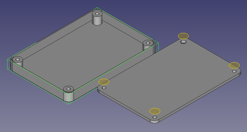
This is a very “Alpha” version of this tool”. It has opportunity for simplification. But is a good starting point. It likely will be more annoying than just doing it by hand. But here it is any way.
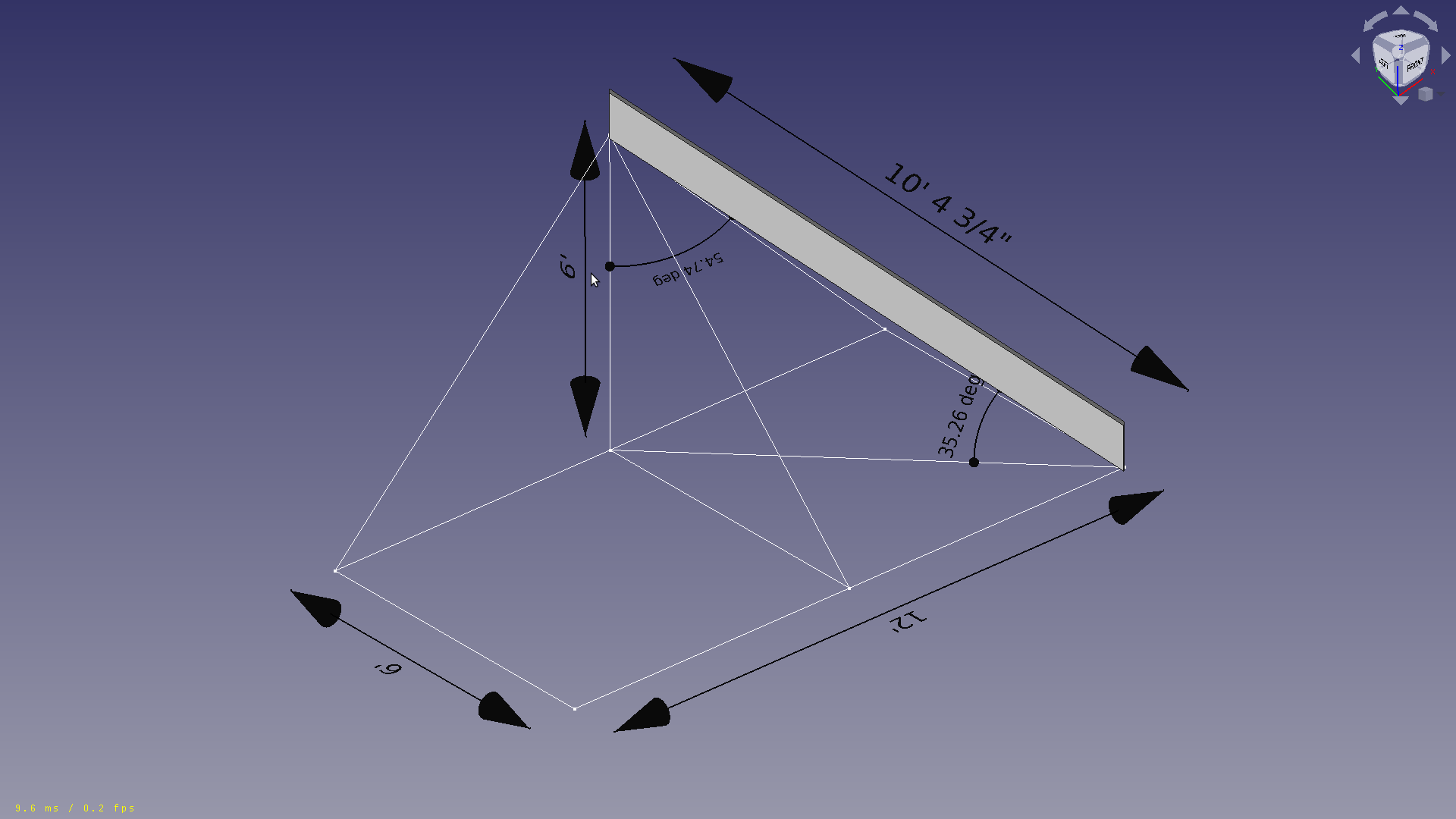
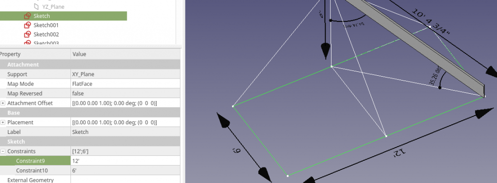
Set the length and width of your roof base, include overhang, so it may not be equal to the ceiling, or ceiling plus plates. This can be done in the “Sketch” ( Constraints, Length, and Width )
Place a Clone.
Make a clone of the Joist to place “in situ”, this joist can then be mirrored / copied if necessary.
TODO:
Name the Sketches appropriately
Name Dimensions.
Fix the “Shortening issue”, the basic length from the corners is used making the Joist shorter than it needs to be.
The current Chamfer is equal. So it will be wrong if the Length and Width are not a 2:1 ratio.
Dimension lines don’t move with sketch edges. ( Can set Draft line vertexes to Sketch vertexes … but that is annoying ).
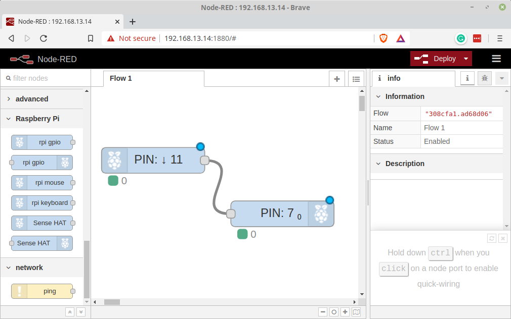
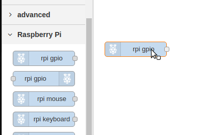
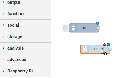
To run this experiment we will use only two nodes rpi-gpio In and rpi-gpio out. Drag one of each onto the Flow edit pane.
When you drop the Nodes the Labeling is updated to reflect the configuration. The two Nodes before wiring will look like this. There has been nothing done to them other than dropping them onto the flow.
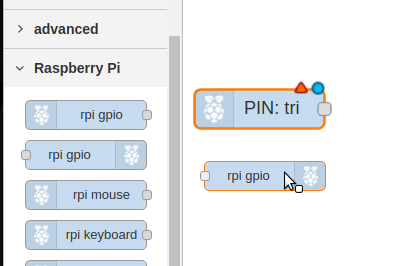
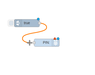
Wire the Nodes together
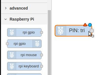
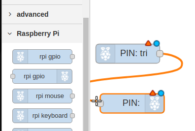
Configure the Input Node
Double Click the rpi-gio In ( it is marked PIN:tri ).
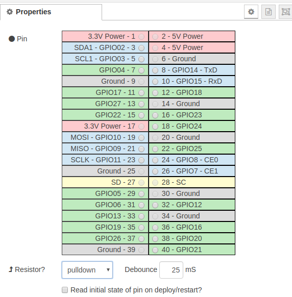
Set the Pin to 11
set the resistor to pull-down
Click Done
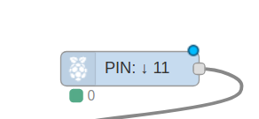
The node Should change to PIN 11
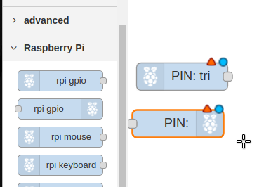
Configure the Output Node
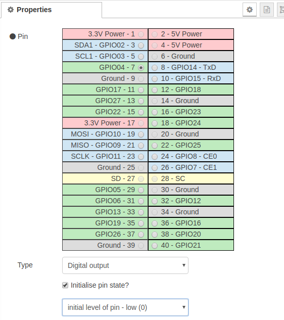
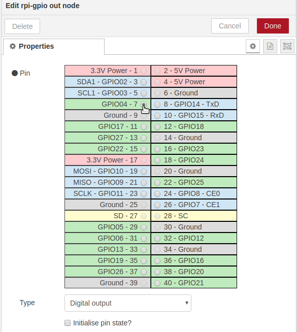
Double Click the rpi-gio out ( it is marked PIN: ).
Set the Pin to 7
Check “Initial pin state?”
Select “initial level of pin -low(0)
Click Done
The Output Node should now be labelled PIN: 7
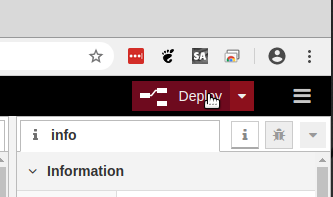
Deploy the Flow
If you have done everything correctly you should now be able to press the button and the LED will light.
Using NodeRED to program your RaspberryPi for GPIO Control.
The basic installation of Raspian includes NodeRED. However you need to start it to use it.
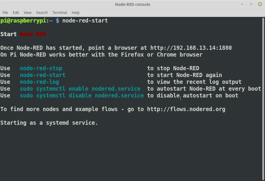
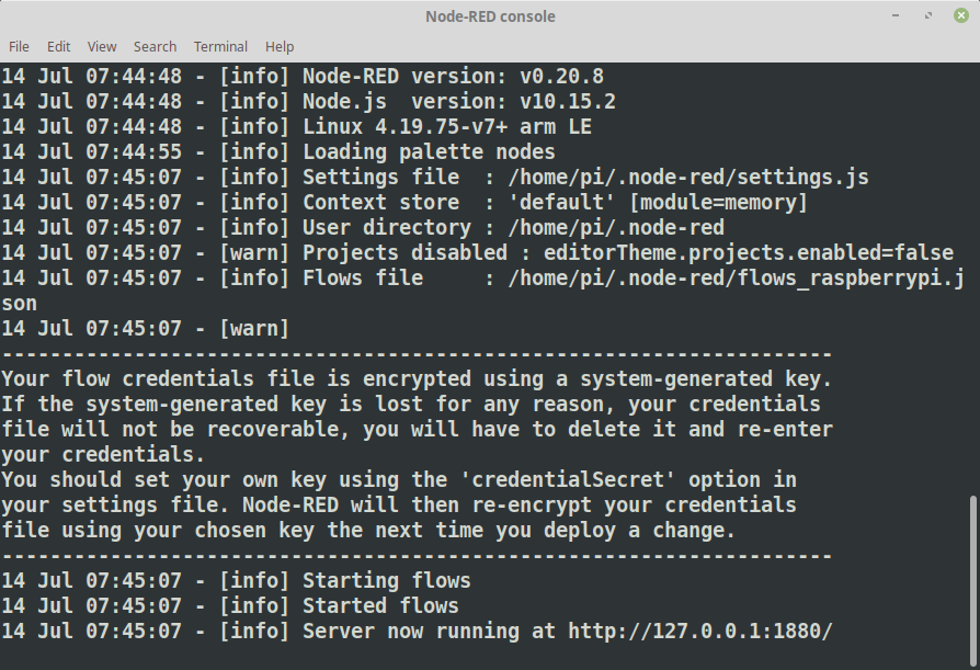
Connect to your Raspberry Pi using your terminal. Issue the NodeRED startup command:
node-red-start
The first line after the “Start Node-RED” will contain where you need to point your browser. Remember that your Raspberry Pi is a fairly small computer so it might take it a little while to load ( possible minutes ).
The console will update once Node-RED has started, it is ready when you see the final line state “Server s now Running …”
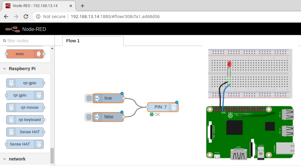
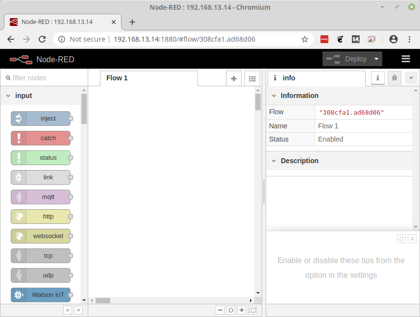
Now we can connect with our browser
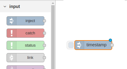
Let’s Add Nodes
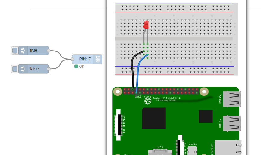
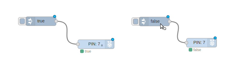
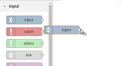
We will use the Inject Node as the “Button”, Drag one of the Inject nodes to the Flow area:
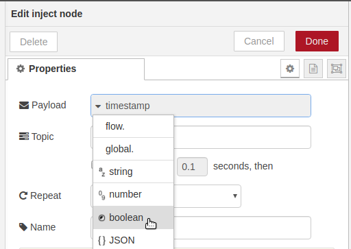
Double click the node to open the edit panel. From the Payload drop-down select boolean and leave the value as True.
Click Done, and you will see that the Inject node now reads as “true”
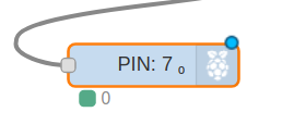
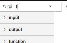
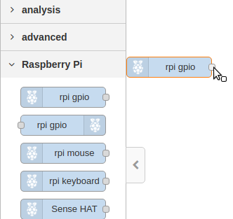
To easily find the Raspberry Pi nodes type rpi in the node search tool at the top left. Drag a single rpi gio Output node to the Flow area and drop it near the Inject Node.
Wire the Inject node to the gpio node:
Double click the PIN Node ( rpi gpio ) to enter into edit mode and select Pin 7 and make certain the type is Digital Output.
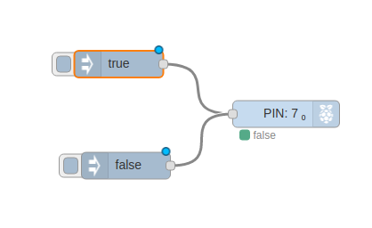
Add the “Off Switch”
Let’s Drag a Second Inject node onto the Flow area
Double click the Inject to edit
Change it to boolean and set the value to false.
Wire the “false” node to the same pin as the true node.
The final step before you can use either of the buttons is to Deploy the Flow.
Clicking the small blue box next to the “true” inject node will turn the LED on and “false” will turn it off.
To get started with controlling and interfacing electronics with the Raspberry Pi, the easiest and safest way is turning a LED On and Off. It is simple but it works.
Interactively, First
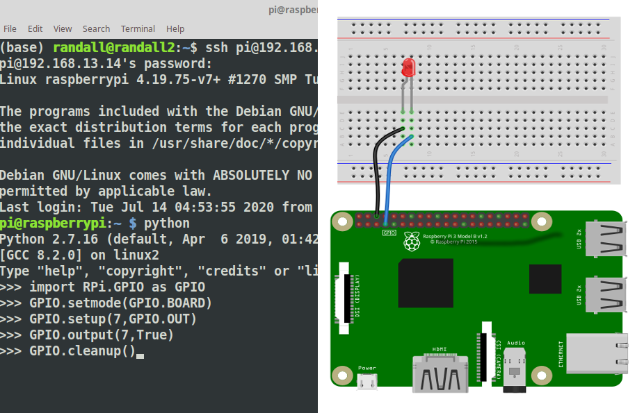
If you have installed Raspian on your Raspberry Pi it comes with Python pre-installed. All you need to do is bring up a terminal and type python <enter> to get to the python console. It looks like this:
The python console let’s you execute code as you go, it is a great way to learn and test small pieces of code.
To control the GPIO pins on the Raspberry Pi we need to add a tool that knows how to control them this is the GPIO Library ( there are others as well ). To add the library we will use the import command. Type the command as show and hit the Enter Key. If done correctly the python console will simply accept it and prompt you for the next line.
>>>import RPi.GPIO as GPIO
>>>
Know that we have the tool we need to tell the python console specifically how to use it. We will be using BOARD mode. This means we will be referring to the PINS as they are physically numbered and laid out. Again you will get no prompt, simply the next line.
>>>import RPi.GPIO as GPIO
>>>GPIO.setmode(GPIO.BOARD)
>>>
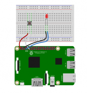
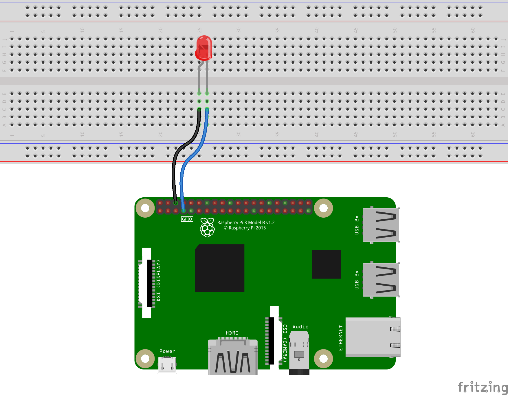
The pins are numbered with Odd Pins in one Row and Even pins in the other. The numbering starts from 1 and 2 next to the Power LED. Pin 1 sits near the inside of the board and Pin 2 near the edge. We will wire Pin 6 and Pin 7 to the LED. Pin 6 is GND ( Ground or Negative ) will be wired to the short leg of the LED or the Cathode. Pin 7 will be wired to the Short leg or the Anode.
Next we need to tell python what to do with pin 7. We use the GPIO.setup() command to indicate that the the Pin will be used for output. The GPIO.OUT is used to indicate output.
>>>GPIO.setup(7,GPIO.OUT)
>>>
To turn the LED on we set the pin to True using GPIO.output()
>>>GPIO.output(7,True)
>>>
To turn the LED off we set the pin to False using GPIO.output()
>>>GPIO.output(7,False)
>>>
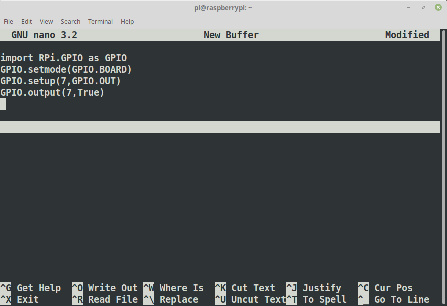
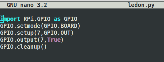
Let’s make a command file.
To complete this on the command line we will use a program called nano. It is a command line based text editor. For more advance python it can be beneficial to use an IDE
Open the editor by executing the nano command and type all the commands from above into the nano windows
When done press CTRL-O, type in the name ledon.py, press enter the CTRL-X
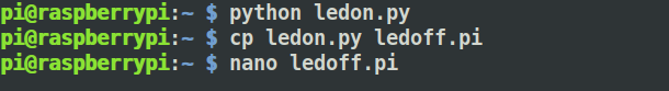
Test the command, type:
python ledon.py
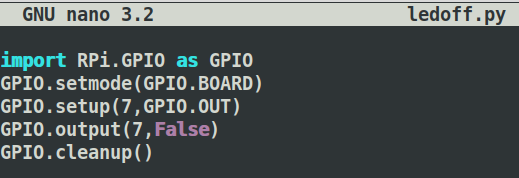
Our Second Command
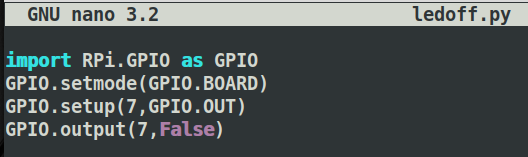
copy the ledon.py to ledoff.py, and open the file with nano ledoff.py
Change the True in line 4 to False
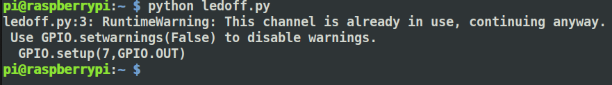
Run the command to turn the led off
python ledoff.py
You will notice there is a warning, let’s take care of that.
Using nano add GPIO.cleanup() to the end of each file
You can now turn the LED On and Off from anywhere you can get a terminal on your Raspberry Pi
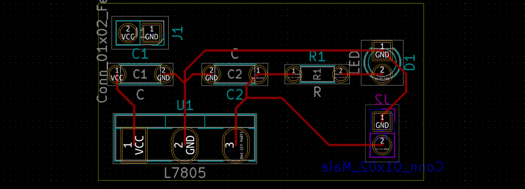
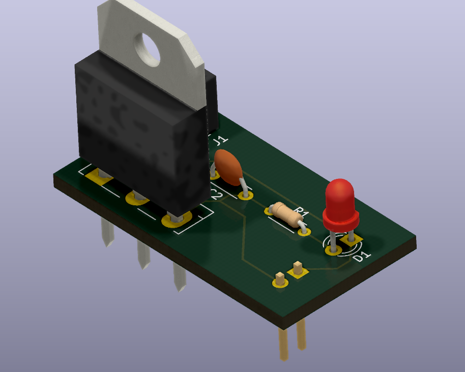
After we have created a Schematic, Annotated and assigned Footprints we can create a PCB and bring in components from the schematic.
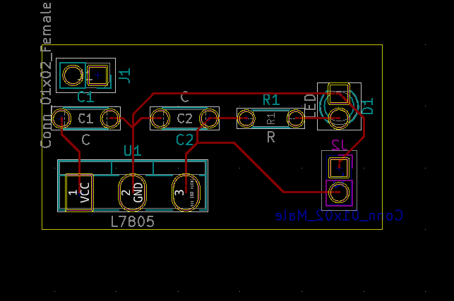
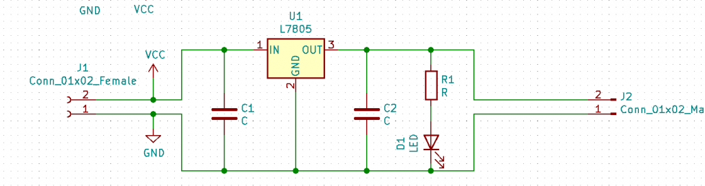
Come Back Soon! This is in progress. Should be done by Friday July 10th. If you just can’t wait you might be able to muddle through with the diagram below. I still need to hookup J1 tho.
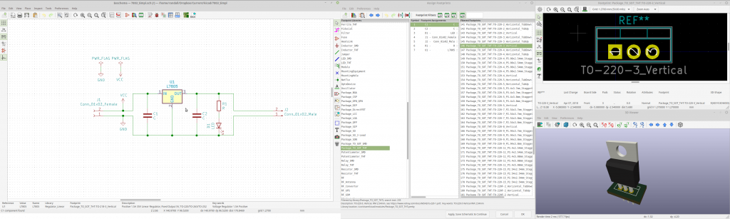
Get the Symbols from Schematic
The first thing we will need to do is “import” the components, using the symbols from the schematic. This process will use the Footprints we assigned previously to place the Components base on the Symbols we selected in the Schematic. ( You might want to read that a few times.)
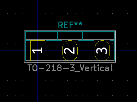
KiCAD abstracts the Symbols on a Schematic from the Components on the PCB. To get from one to the other we need to assign a Footprint to each Symbol. There are multiple ways to accomplish this, we will start with the batch tool to do all of them at once for the Basic 7805.
This Tutorial will cover the use of KiCAD to create a Schematic, PCB and send that PCB to a Manufacturer. It is not a tutorial in the underlying electronics or electronic theory. Use of circuits in this tutorial are at your own risk and should be limited to educational purposes only.
Creating the Schematic
The first step in getting a circuit board ready to be manufactured is to create a schematic. This Step-By-Step how-to will walk through the creation of a very basic implementation of the L7805 5v Power Regulator.
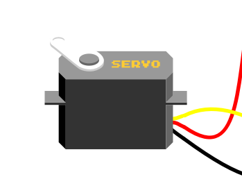
In order to easily code for a Servo motor, it is best to use a library. This example uses the Servo.h library from barraganstudio.com
The code below is from the example, but with the pin changed and the comments removed.
/* Sweep
by BARRAGAN http://barraganstudio.com
This example code is in the public domain.modified 8 Nov 2013
by Scott Fitzgerald
http://www.arduino.cc/en/Tutorial/Sweep
*/
This website uses cookies to improve your experience. We'll assume you're ok with this, but you can opt-out if you wish. Cookie settingsACCEPT
Privacy & Cookies Policy
Privacy Overview
This website uses cookies to improve your experience while you navigate through the website. Out of these cookies, the cookies that are categorized as necessary are stored on your browser as they are essential for the working of basic functionalities of the website. We also use third-party cookies that help us analyze and understand how you use this website. These cookies will be stored in your browser only with your consent. You also have the option to opt-out of these cookies. But opting out of some of these cookies may have an effect on your browsing experience.
Necessary cookies are absolutely essential for the website to function properly. This category only includes cookies that ensures basic functionalities and security features of the website. These cookies do not store any personal information.
Any cookies that may not be particularly necessary for the website to function and is used specifically to collect user personal data via analytics, ads, other embedded contents are termed as non-necessary cookies. It is mandatory to procure user consent prior to running these cookies on your website.