Posted on Leave a comment

RaspberryPi – 16×02 LCD Display in Python

If you want details from the source, the library we are using here is fully documented at https://rplcd.readthedocs.io/en/stable/

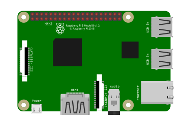
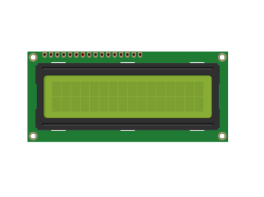
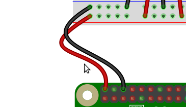
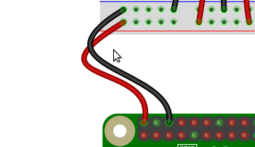
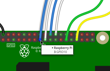
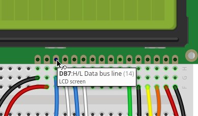
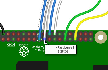
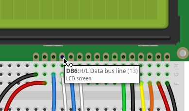
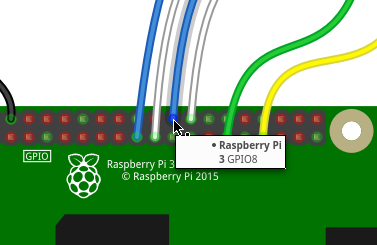
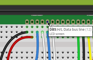
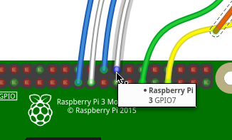
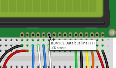
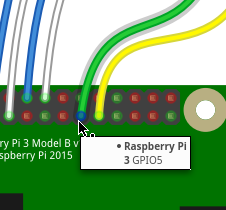
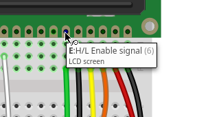
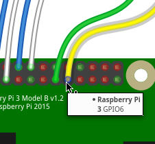
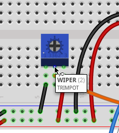
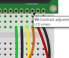
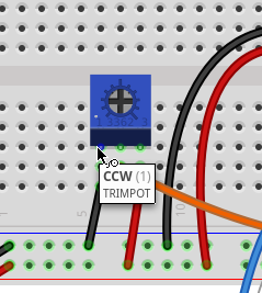
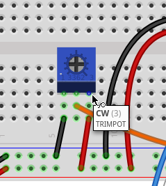
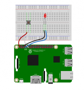
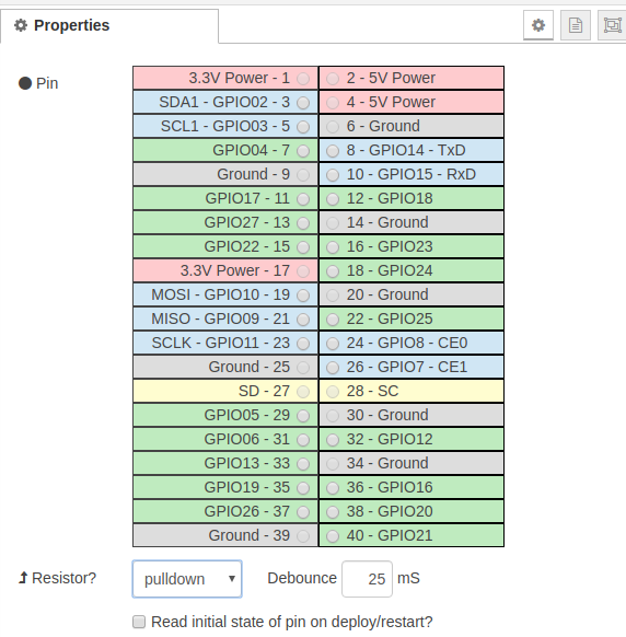
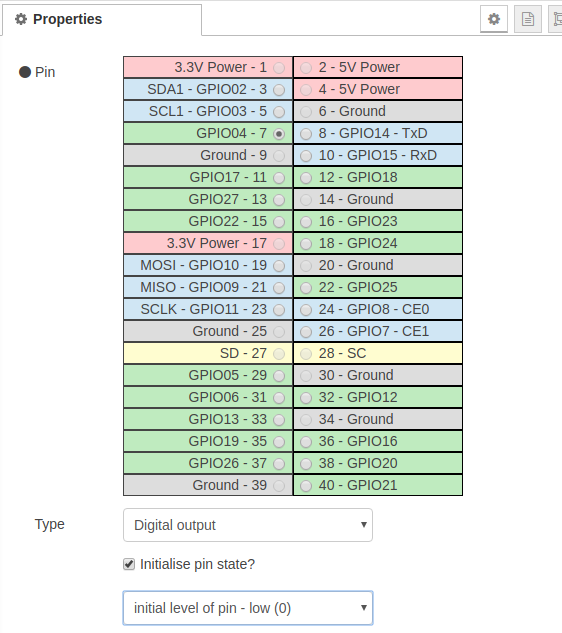
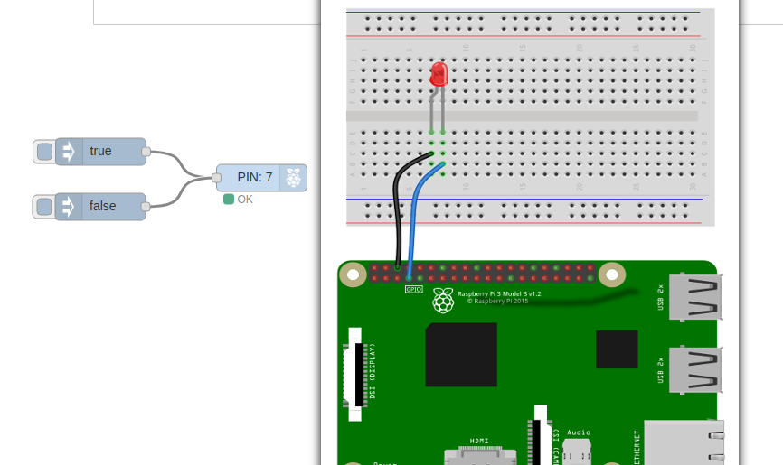
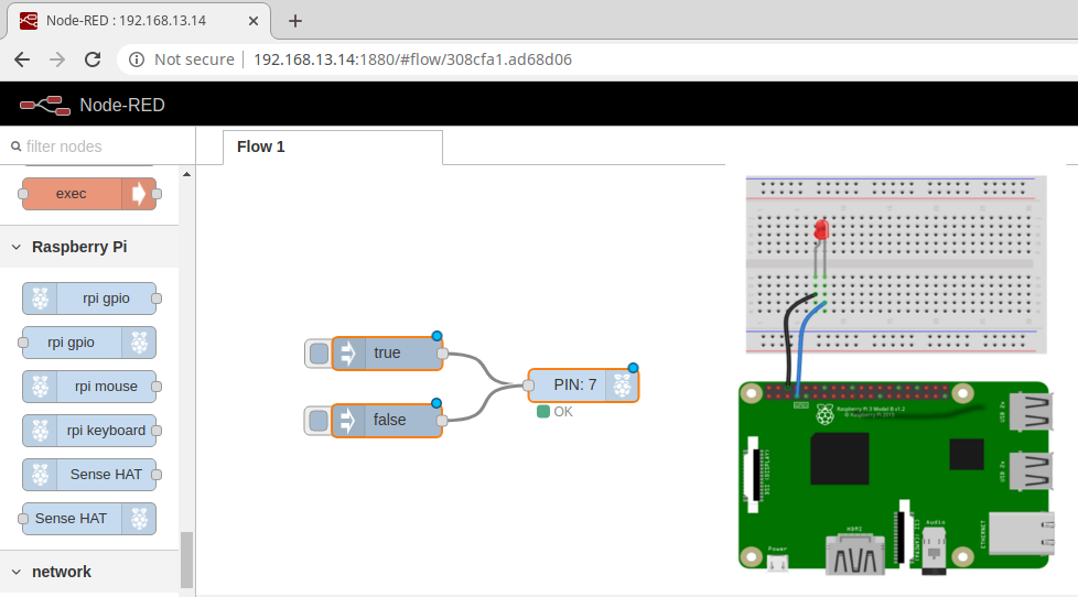
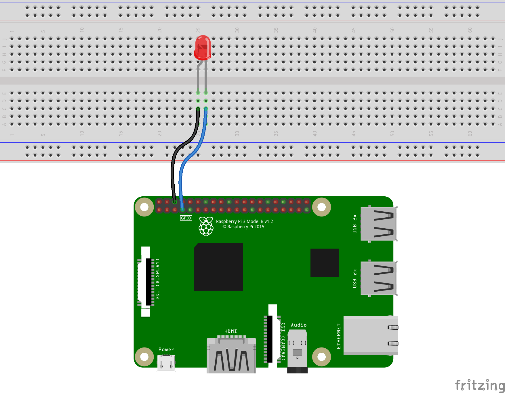
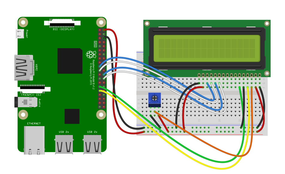
The Fritzing Diagram can be helpful in wiring up the Pi and the LCD, Fristzing contain pin identifications if you hover over the pin.

The Bare Minimum to get a message on Screen
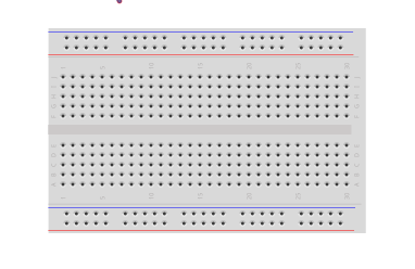
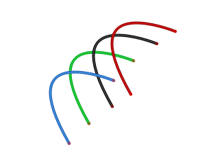
Wire the Components

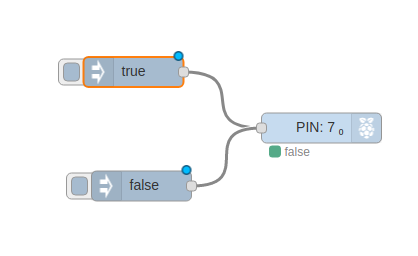
The Wiring for the Python version of code is the same as the NodeRED version. Follow the wiring section on that post and return here for the code.
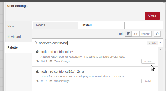
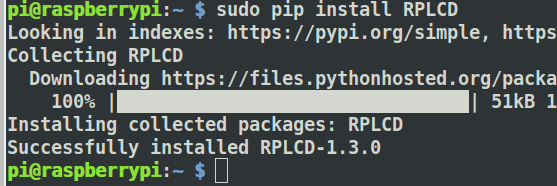
Get The Library

$ sudo pip install RPLCD
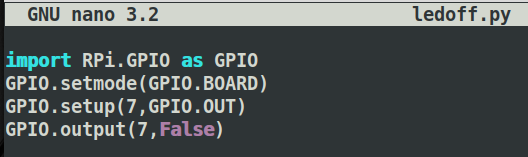
Coding Python

The beauty of coding for hardware like an LCD on the Raspberry Pi is that the code is already present where it will be executing. There is no need to compile and upload for a Python Script.

If you prefer to code on your desktop it as simple as copying the resulting Python file to your Raspberry Pi.

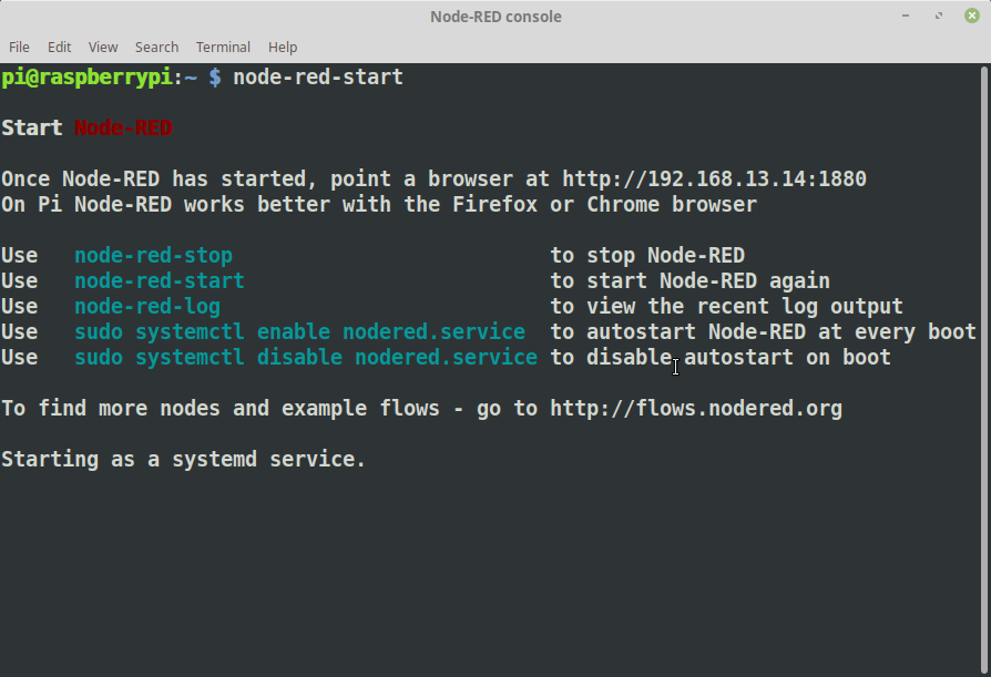
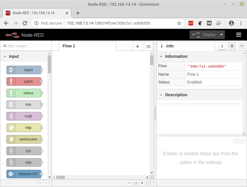
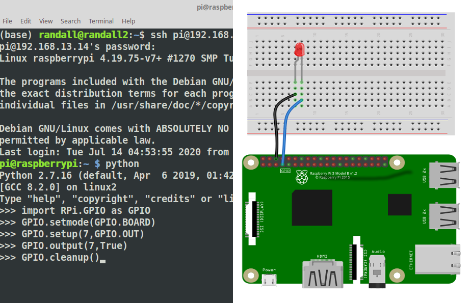
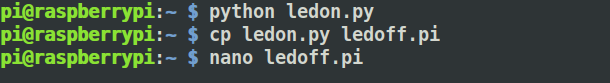
For this activity we will be coding in the bash shell via an ssh connection.

ssh pi@192.168.13.14
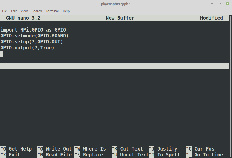
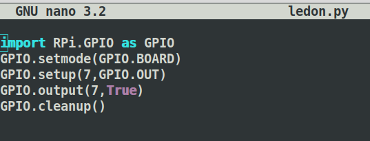
nano pi_lcd.py

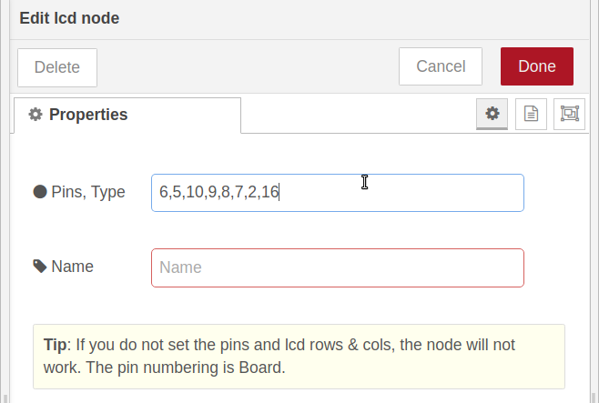
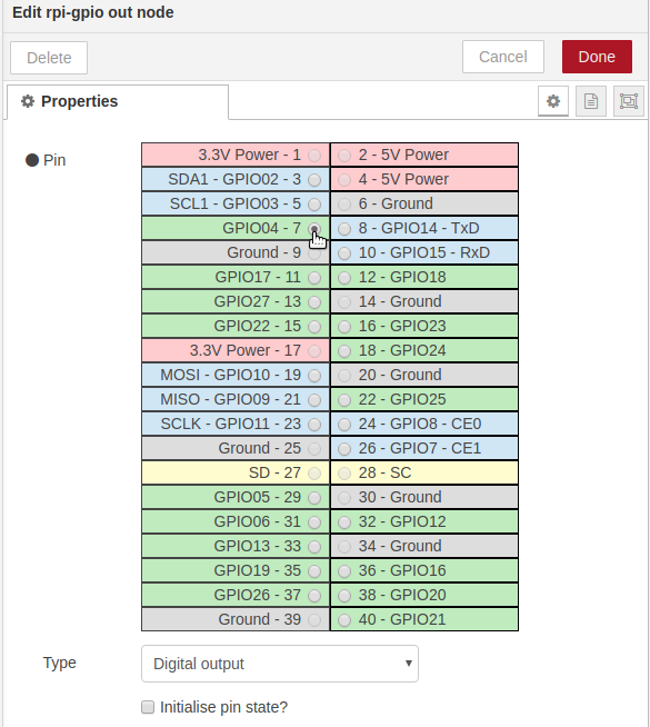
Define the pins that will be used

We will use simple variables to define each of the pins connecting the LCD to the Pi. They could be more abbreviated but to help with clarity we will use longer names.

ENABLE = 31
REGISTER_SELECT = 29
DATA_PIN_D7 = 26
DATA_PIN_D6 = 24
DATA_PIN_D5 = 21
DATA_PIN_D4 = 19

Let’s create any LCD Object using the VAriables we setup above. The RPLCD library does all the hard work all we need to do is import the library and then create an “instance”.

First import the Library

from RPLCD.gpio import CharLCD

Now using the variables we set up earlier we will create the LCD object. The CharLCD class uses keyword args for input. So each argument is a keyword and the value being assigned.

my_lcd = CharLCD(cols=16, rows=2, pin_rs=REGISTER_SELECT, pin_e=ENABLE, pins_data=[DATA_PIN_D7,DATA_PIN_D6,DATA_PIN_D5,DATA_PIN_D4]

That’s all we need, add a line with what text you want to display and you are good to go.

my_lcd.write(u'Message of Hope')

Posted on 1 Comment

RaspberryPi – 16×02 LCD Display on NodeRED

Materials

  • Raspberry Pi 3
  • 16×2 LCD
  • Breadboard
  • Hookup Wire
  • Trimmer / Potentiometer

Use the Pallete manager to install node-red-contrib-lcd

https://flows.nodered.org/node/node-red-contrib-lcd

Flows

Add the LCD Node to your flow.

The LCD node requires a string indiacting whcih pins of the LCD are connected to which pins of the pi. The format is shown when you double click the node to configure it.

The “Pins, Type” field will give you the format \: RS, EN, D7, D6, D5, D4, ROW, COL

The pin numbering using Board numbering is 6,5,10,9,8,7,2,16

Add the pin numbering and click done.

Board Numbering: 6,5,10,9,8,7,2,16

GPIO Numbering : 31,29, 26,24,21,19, 2,16

Board numbering is simply sequential with even numbers from 2 on the outer row and odd numbers from 1 on the inner row.

Add an inject node:

Connect the inject node to the LCD node.

Double click the inject node and add a string to,

That’s all there is on the NodeRED end, you can deploy now or wait until after wiring.

If you don’t want to wire up the Flow you can just copy in this:

Wiring

The Full Fritzing Diagram is on TeachersPayTeachers.com

Let’s wire up our Pi and LCD as follows. Some color coding can help but the colors are not important.

Connect a Wire from “PIN 2” on the RaspberryPI to the Lower rail ( Red ) on your breadboard. This is +5volts and will be used to power the LCD and the LCD Backlight

Connect a second wire from PIN 6 to the Blue Rail on the Breadboard, this will provide the GRound or NEG for the LCD.

Connect the DATA Lines

We can connect the four Data lines from the LCD to any GPIO Pins on the RaspberryPi. In this example, GPIO 7,8,9,10 were selected for visual location and consecutive numbering. As shown we will be using Blue and White wires for the DATA lines but any color can be used.

Connect GPIO10 to the Breadboard directly below the LCD Pin As Shown. It will be the third pin from the left and likely labelled D8, Pin 14 or sometimes DB7.

Connect GPIO 9 to D7 ( DB6 )

Connect GPIO 8 to D6 ( DB5 )

Connect GPIO 7 to D6 ( DB5 )

Connect the Control Lines

There are only two lines that will be used to control the LCD. Enable and Command Mode. The enable line is basically the on/off switch for the LCD connected to the PI and the Command Mode or “Register Select” informs the LCD if it will be receiving a command to act upon or letters to display.

Connect GPIO5 to the Breadboard colum directly beneath the E pin on the LCD.

Connect GPIO6 to the Breadboard colum directly beneath the RS Pin on the LCD

Wire the Contrast Knob

Trimmer/PotentiometerPotentiometer ) to the LCD VO ( Contrast ). Make sure you coonect the “Wiper” the cneter in this case to the column directly beneath the VO

Connect the Dimmer s( Trimmer/Potentiometer ) legs CW and CCW to +5v and Ground, the polarity of these two determine whether the contrast is increased with a Clockwise turn or a Counter-Clockwise turn.

Deploy the Node and Try a Message

Posted on Leave a comment

Linux Server System Auditing – Quick Start

I wanted a tool to quickly show me some of the basic things I needed to work on to harden the security on the various servers I am running. A sort of security checklist. The first tool I have been trying out is the community version of Lynis, and I have enjoyed it so far. With a “Hardeining index” from 1-100, it gives me a great indicator of how I am progressing.

Once installed ( and they have detailed install instructions for many systems ) it is as easy as a single command to get you started:

lynis audit system

you will get a giant ( not too giant ) list of the status of your system and actionable items.

For my scan I fixed a few things moving from 66 to 72 in my first hardening session.

Posted on Leave a comment

FreeCAD Framing – Hip Roof Joist “Calculator”

This is a very “Alpha” version of this tool”. It has opportunity for simplification. But is a good starting point. It likely will be more annoying than just doing it by hand. But here it is any way.

Using:

Set the length and width of your roof base, include overhang, so it may not be equal to the ceiling, or ceiling plus plates. This can be done in the “Sketch” ( Constraints, Length, and Width )

Place a Clone.

Make a clone of the Joist to place “in situ”, this joist can then be mirrored / copied if necessary.

TODO:

  • Name the Sketches appropriately
  • Name Dimensions.
  • Fix the “Shortening issue”, the basic length from the corners is used making the Joist shorter than it needs to be.
  • The current Chamfer is equal. So it will be wrong if the Length and Width are not a 2:1 ratio.
  • Dimension lines don’t move with sketch edges. ( Can set Draft line vertexes to Sketch vertexes … but that is annoying ).
  • Angle Dimensions Don’t ReCalc or Move

Posted on Leave a comment

Raspberry Pi – NodeRED Button

This simple experiment will demonstrate using a push button to light a LED.

Adding a Push-Button to an LED in Raspberry Pi doesn’t get much easier than with NodeRED, two nodes, and you are done.

The Fritzing Diagram is availble for download

Wire the LED and Button as shown in the Diagram

  • Pin 1 – Left side of button
  • Pin 11 – Right side of button
  • Pin 6 – Led Cathode ( Short Wire / Flat Side )
  • Pin 7 – Led Anode ( Long Wire )

If you simply want to try this Flow, you can import this:

[{"id":"60410dd4.757164","type":"rpi-gpio out","z":"308cfa1.ad68d06","name":"","pin":"7","set":true,"level":"0","freq":"","out":"out","x":253.4615135192871,"y":348.46156311035156,"wires":[]}]

To run this experiment we will use only two nodes rpi-gpio In and rpi-gpio out. Drag one of each onto the Flow edit pane.

When you drop the Nodes the Labeling is updated to reflect the configuration. The two Nodes before wiring will look like this. There has been nothing done to them other than dropping them onto the flow.

Wire the Nodes together

Configure the Input Node

  1. Double Click the rpi-gio In ( it is marked PIN:tri ).
  2. Set the Pin to 11
  3. set the resistor to pull-down
  4. Click Done

The node Should change to PIN 11

Configure the Output Node

  1. Double Click the rpi-gio out ( it is marked PIN: ).
  2. Set the Pin to 7
  3. Check “Initial pin state?”
  4. Select “initial level of pin -low(0)
  5. Click Done

The Output Node should now be labelled PIN: 7

Deploy the Flow

If you have done everything correctly you should now be able to press the button and the LED will light.

Posted on Leave a comment

Raspberry Pi – NodeRed LED Blink

Using NodeRED to program your RaspberryPi for GPIO Control.

The basic installation of Raspian includes NodeRED. However you need to start it to use it.

Connect to your Raspberry Pi using your terminal. Issue the NodeRED startup command:

node-red-start

The first line after the “Start Node-RED” will contain where you need to point your browser. Remember that your Raspberry Pi is a fairly small computer so it might take it a little while to load ( possible minutes ).

The console will update once Node-RED has started, it is ready when you see the final line state “Server s now Running …”

Now we can connect with our browser

Let’s Add Nodes

We will use the Inject Node as the “Button”, Drag one of the Inject nodes to the Flow area:

Double click the node to open the edit panel. From the Payload drop-down select boolean and leave the value as True.

Click Done, and you will see that the Inject node now reads as “true”

To easily find the Raspberry Pi nodes type rpi in the node search tool at the top left. Drag a single rpi gio Output node to the Flow area and drop it near the Inject Node.

Wire the Inject node to the gpio node:

Double click the PIN Node ( rpi gpio ) to enter into edit mode and select Pin 7 and make certain the type is Digital Output.

Add the “Off Switch”

Let’s Drag a Second Inject node onto the Flow area

Double click the Inject to edit

Change it to boolean and set the value to false.

Wire the “false” node to the same pin as the true node.

The final step before you can use either of the buttons is to Deploy the Flow.

Clicking the small blue box next to the “true” inject node will turn the LED on and “false” will turn it off.

Posted on Leave a comment

Raspberry Pi – Getting Started with an LED

To get started with controlling and interfacing electronics with the Raspberry Pi, the easiest and safest way is turning a LED On and Off. It is simple but it works.

Interactively, First

If you have installed Raspian on your Raspberry Pi it comes with Python pre-installed. All you need to do is bring up a terminal and type python <enter> to get to the python console. It looks like this:

The python console let’s you execute code as you go, it is a great way to learn and test small pieces of code.

To control the GPIO pins on the Raspberry Pi we need to add a tool that knows how to control them this is the GPIO Library ( there are others as well ). To add the library we will use the import command. Type the command as show and hit the Enter Key. If done correctly the python console will simply accept it and prompt you for the next line.

>>>import RPi.GPIO as GPIO
>>>

Know that we have the tool we need to tell the python console specifically how to use it. We will be using BOARD mode. This means we will be referring to the PINS as they are physically numbered and laid out. Again you will get no prompt, simply the next line.

>>>import RPi.GPIO as GPIO
>>>GPIO.setmode(GPIO.BOARD)
>>>

The pins are numbered with Odd Pins in one Row and Even pins in the other. The numbering starts from 1 and 2 next to the Power LED. Pin 1 sits near the inside of the board and Pin 2 near the edge. We will wire Pin 6 and Pin 7 to the LED. Pin 6 is GND ( Ground or Negative ) will be wired to the short leg of the LED or the Cathode. Pin 7 will be wired to the Short leg or the Anode.

Next we need to tell python what to do with pin 7. We use the GPIO.setup() command to indicate that the the Pin will be used for output. The GPIO.OUT is used to indicate output.

>>>GPIO.setup(7,GPIO.OUT)
>>>

To turn the LED on we set the pin to True using GPIO.output()

>>>GPIO.output(7,True)
>>>

To turn the LED off we set the pin to False using GPIO.output()

>>>GPIO.output(7,False)
>>>

Let’s make a command file.

To complete this on the command line we will use a program called nano. It is a command line based text editor. For more advance python it can be beneficial to use an IDE

Open the editor by executing the nano command and type all the commands from above into the nano windows

When done press CTRL-O, type in the name ledon.py, press enter the CTRL-X

Test the command, type:

python ledon.py

Our Second Command

copy the ledon.py to ledoff.py, and open the file with nano ledoff.py

Change the True in line 4 to False

Run the command to turn the led off

python ledoff.py

You will notice there is a warning, let’s take care of that.

Using nano add GPIO.cleanup() to the end of each file

You can now turn the LED On and Off from anywhere you can get a terminal on your Raspberry Pi

Posted on Leave a comment

Basic 7805 – KiCAD Beginner – PCB

After we have created a Schematic, Annotated and assigned Footprints we can create a PCB and bring in components from the schematic.

Come Back Soon! This is in progress. Should be done by Friday July 10th. If you just can’t wait you might be able to muddle through with the diagram below. I still need to hookup J1 tho.

Get the Symbols from Schematic

The first thing we will need to do is “import” the components, using the symbols from the schematic. This process will use the Footprints we assigned previously to place the Components base on the Symbols we selected in the Schematic. ( You might want to read that a few times.)

Continue reading Basic 7805 – KiCAD Beginner – PCB
Posted on Leave a comment

Basic 7805 – KiCAD Beginner – Schematic

From to Design to Circuit Board.

This Tutorial will cover the use of KiCAD to create a Schematic, PCB and send that PCB to a Manufacturer. It is not a tutorial in the underlying electronics or electronic theory. Use of circuits in this tutorial are at your own risk and should be limited to educational purposes only.

Creating the Schematic

The first step in getting a circuit board ready to be manufactured is to create a schematic. This Step-By-Step how-to will walk through the creation of a very basic implementation of the L7805 5v Power Regulator.

Continue reading Basic 7805 – KiCAD Beginner – Schematic