
Teaching Thermal Properties using the “Design a Thermos” style lesson. It is a tried and true approach. This Lesson Plan Adjunct attempts to add elements of coding and design into the mix.
Part I – Wiring the Arduino

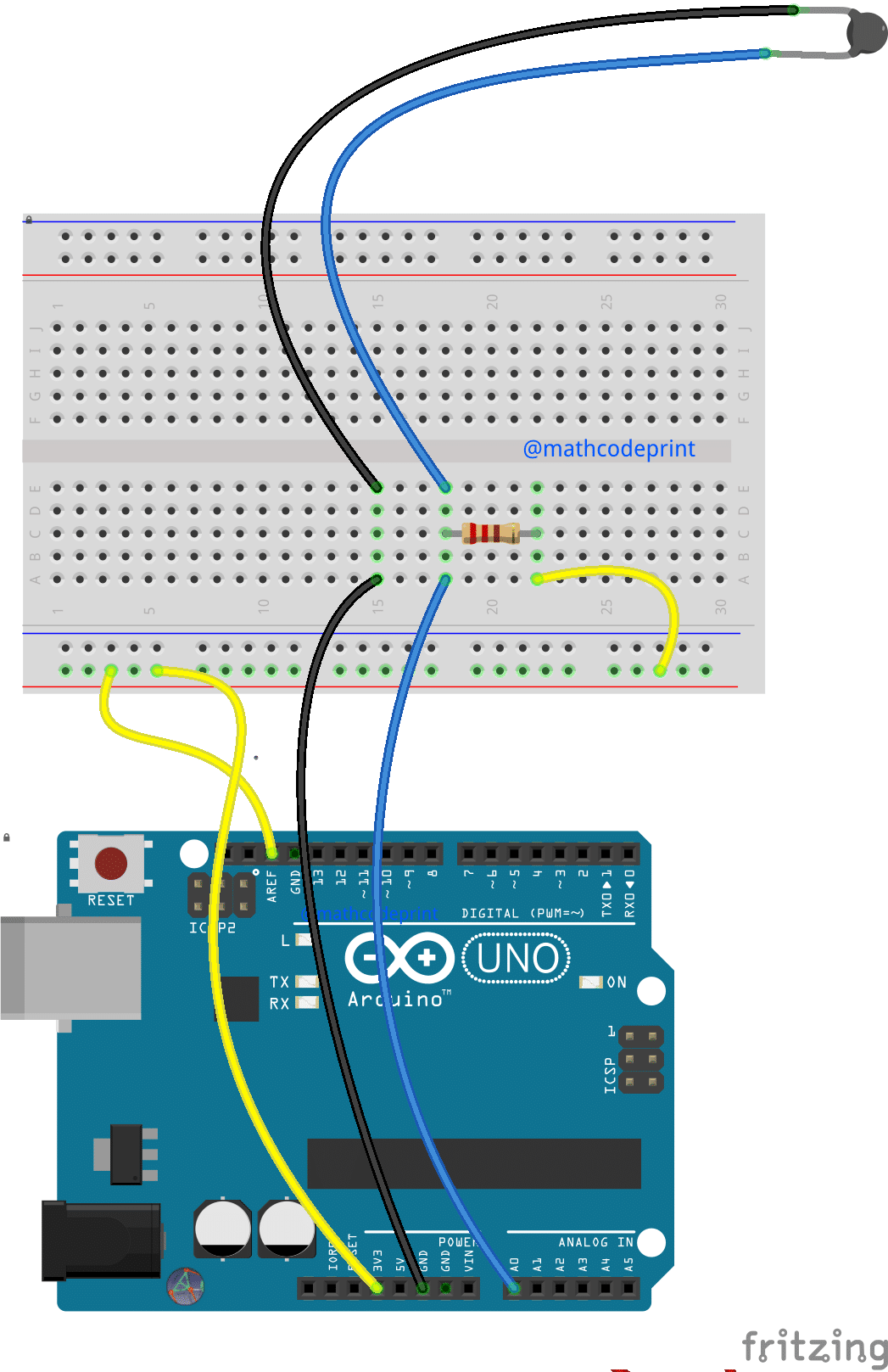
The wiring of the Arduino to the Thermistor is very straight forward many students will be able to achieve the wiring with just the diagram.
- Connect a wire from the 3.3v pin ( on the power header ) to the end of the red row.
- Connect a wire from the red row to the AREF pin on the Arduino
- Connect a wire from A0 to position A,20 on the breadboard
- Connect a wire ( Black is good for this but not required ) from GND to position A,15 on the breadboard
- Insert one end of the resistor into the same column as the wire in step 3
- The other end of the resistor can be inserted into the breadboard to position C,25
- Connect a wire from position x.y to one end of the Thermistor
- Connect a wire from the other end of the Thermistor to position E,15
- Finally, connect a wire from the red power rail to the second end of the resistor
The circuit used here is what is known as a voltage divider. The voltage divider uses a known voltage that is divided into two resistors, one with a known value and one with a un-known value. With the known value and the known voltage we can calculate the resistance of the unknown resistor, in this case, the Thermistor.
The reason this can give us the temperature is that the resistance of the Thermistor changes based on its temperate
Instructor Notes:
The positions on the breadboard are mostly arbitrary, however, using a consistent position allows the instructor to easily identify problem connections when guiding a group of students.
The wire colors are also arbitrary but using coloring standards can help identify issues that would otherwise be confused by random wire color choices.
Part II – Load the Code
The code can be downloaded from this web-site or from GitHub
You can load this code via the standard Arduino IDE, or the online editor at create.ardunio.cc
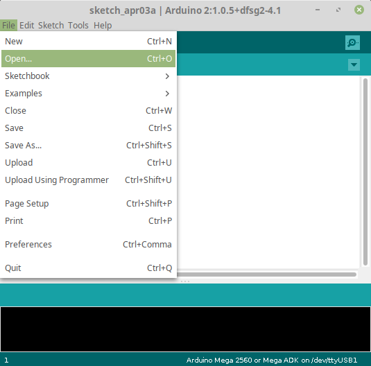
Loading Code Using the Arduino IDE
If you do not already have the IDE you can download it from here: Arduino Software
Go to the section titled “Download the Arduino IDE” and select the appropriate option
ALERT! : Often you may require various permissions to download and install this option. Make sure to communicate with your administrator.
Part III – Run the experiment
To run the experiment the Student should have their computing device and wired Arduino ready.
- Place the Thermistor Probe into the Thermos using a 1/4 inch hole or other available openings.
- Open the Serial console on the Arduino
- Press the Reset button on your Arduino
- The Serial Console should start receiving data at the given intervals.
- When the experiment is complete copy the contents of the Serial Console into the spreadsheet of your choice.
Changing Sample Period and Frequency
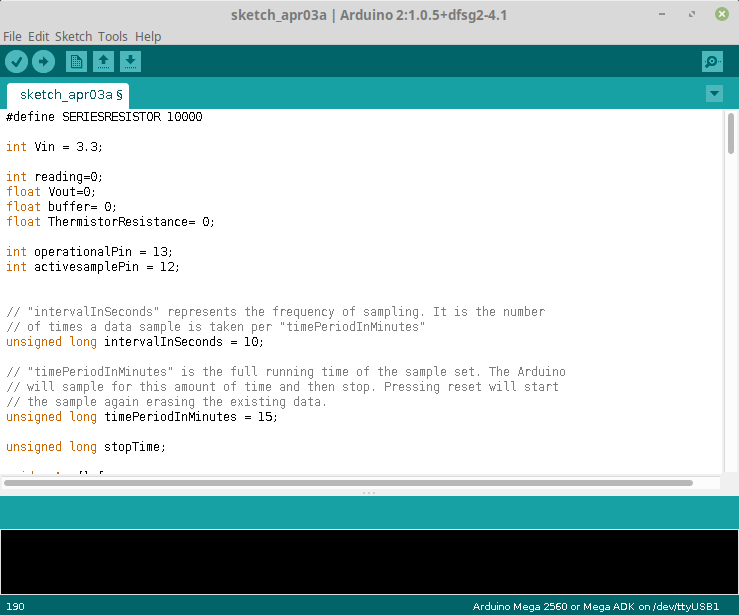
The provided code has to Global Variables
- intervalInSeconds
- timePeriodInMinutes
timePeriodInMinutes is used to change the entire duration of you experiment.
intervalInSecond is used to set the number of samples collected within timePeriodInMinutes
If you change these values you will need to re-load your code onto your Arduino.
Parts List
- Arduino UNO ( or similar )
- USB Chord
- Breadboard
- Temperature Probe / Thermistor ( Stainless Steel 10k 3950 PTC Temp Sensor Probe )
- 10K ohm resistor
- Hookup Wire / Jumpers
Understanding our Thermistor
In this lesson, we are using a PTC Thermistor. PTC is the Acronym for Positive Temperature Co-efficient. This means that as the temperature increases the resistance of this Thermistor increases.
Additional Resources
- Spreadsheet with preloaded data. – Google Sheets
- An in-depth understanding about Thermistor operation: https://www.allaboutcircuits.com/projects/measuring-temperature-with-an-ntc-thermistor/
Buy the Kit – [product sku=”ATHERM11″]