Certainly! Here’s a revised version of the tutorial that includes code for looping through multiple digits on a seven-segment LED display:
Materials Required
- Arduino Uno
- Breadboard
- Seven-segment LED display (common cathode or common anode)
- Jumper wires
- USB cable (Type A to Type B)
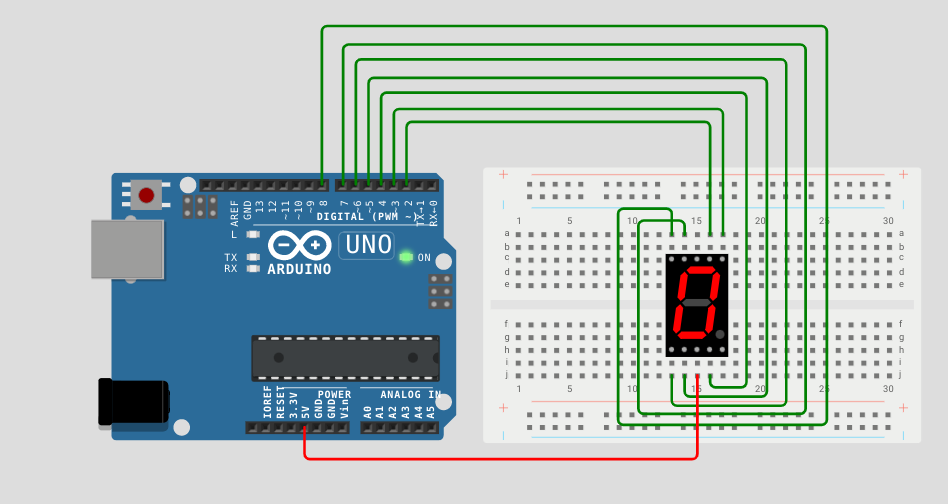
Wiring the Circuit
Step 1: Place the Arduino Uno on the breadboard.
- Position the Arduino Uno on the breadboard, aligning the USB port side with the longer section of the breadboard.
Step 2: Connect power and ground.
- Connect the 5V pin of the Arduino to the positive rail (+) on the breadboard.
- Connect the GND pin of the Arduino to the ground rail (-) on the breadboard.
Step 3: Connect the segment pins of the seven-segment LED display.
- Identify the segment pins on your seven-segment LED display. The common cathode display will have a common cathode pin, while the common anode display will have a common anode pin.
- Connect the segment pins of the seven-segment LED display to the Arduino Uno using jumper wires. Ensure that the pin connections match those specified in the code examples I provided earlier. For example, connect segment pin “a” to Arduino pin 2, segment pin “b” to Arduino pin 3, and so on.
Step 4: Connect the common pin of the seven-segment LED display.
- For a common cathode display, connect the common cathode pin to the ground rail (-) on the breadboard.
- For a common anode display, connect the common anode pin to the positive rail (+) on the breadboard.
Step 5: Load the code onto the Arduino Uno.
- Open the Arduino Integrated Development Environment (IDE) on your computer. If you don’t have it installed, you can download it from the official Arduino website (https://www.arduino.cc/en/software).
- Connect the Arduino Uno to your computer using the USB cable.
- In the Arduino IDE, select the appropriate board by navigating to “Tools” > “Board” > “Arduino Uno”.
- Select the appropriate port by navigating to “Tools” > “Port” and selecting the port that corresponds to your Arduino Uno.
- Copy and paste the following code into the Arduino IDE:
// Pin Definitions
const int segmentPins[] = {2, 3, 4, 5, 6, 7, 8}; // Pins connected to segments a, b, c, d, e, f, g
const int digitPins[] = {9, 10, 11, 12}; // Pins connected to digit 1, 2, 3, 4

// Digit patterns for numbers 0 to 9
const byte digitPatterns[] = {
B11111100, // 0
B01100000, // 1
B11011010, // 2
B11110010, // 3
B01100110, // 4
B10110110, // 5
B10111110, // 6
B11100000, // 7
B11111110, // 8
B11110110 // 9
};

void setup() {
// Set segment and digit pins as outputs
for (int i = 0; i < 7; i++) {
pinMode(segmentPins[i], OUTPUT);
}

for (int i = 0; i < 4; i++) {
pinMode(digitPins[i], OUTPUT
\void loop() {
  int number = 1234; // Number to display

  displayNumber(number); // Display the number
  delay(1000);           // Wait for 1 second
}

void displayNumber(int number) {
  // Extract individual digits from the number
  int digits[4];
  digits[0] = number / 1000;
  digits[1] = (number / 100) % 10;
  digits[2] = (number / 10) % 10;
  digits[3] = number % 10;

  // Loop through each digit
  for (int i = 0; i < 4; i++) {
    // Set the current digit pin high
    digitalWrite(digitPins[i], HIGH);

    // Display the digit pattern on the segments
    for (int j = 0; j < 7; j++) {
      digitalWrite(segmentPins[j], bitRead(digitPatterns[digits[i]], j));
    }

    // Delay to hold the digit for a short period
    delay(5);

    // Set the current digit pin low to turn it off
    digitalWrite(digitPins[i], LOW);
  }
}
);
In this code, the loop() function continuously repeats the process of displaying the number on the seven-segment LED display and then waiting for 1 second before displaying the next number.
The displayNumber() function takes the number as input and extracts individual digits from it. It then iterates through each digit, sets the corresponding digit pin high to select it, and displays the digit pattern on the segments of the seven-segment LED display. After a short delay, the digit pin is set low to turn it off.
To customize the displayed number, modify the number variable in the loop() function.
After completing these steps, verify the wiring connections and click on the “Upload” button (right arrow icon) in the Arduino IDE to compile and upload the code to the Arduino Uno. The Arduino Uno will then run the code and display the desired numbers on the seven-segment LED display.
Remember to adjust the pin numbers in the code if you have connected the segments or digit pins to different Arduino pins.
That’s it! You have successfully wired an Arduino Uno with a seven-segment LED display using a breadboard and loaded the code to display multiple digits.
