
Make a single LED Blink using Raspberry PI GPIO and Python.
Using the RPi.GPIO library we can program the LED to blink on and off. The GPIO library gives us easy access to the Pins of the Raspberry Pi.
Take a moment to print out this guide, with a custom template to make hookup dead simple.
https://www.teacherspayteachers.com/Product/Raspberry-Pi-Blink-Project-Guide-5959017
Requirements
- A Raspberry Pi 2/3/4
- A single LED
- 2 Hookup Wires
- A 2.2K Ohm Resistor
- Prototyping Breadboard
- A Raspberry Pi with Rasbian Installed and Running
- Access to the Shell on the Raspberry Pi
First Let’s Wire Up the Pi and the LED
Get Ready
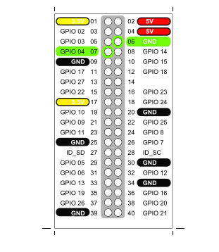
It can be extremely useful to get a PIN template and push it onto the Pins of the PI
I got mine from her : https://www.computerhilfen.de/english/raspberry-pi-gpio-paper-template.html
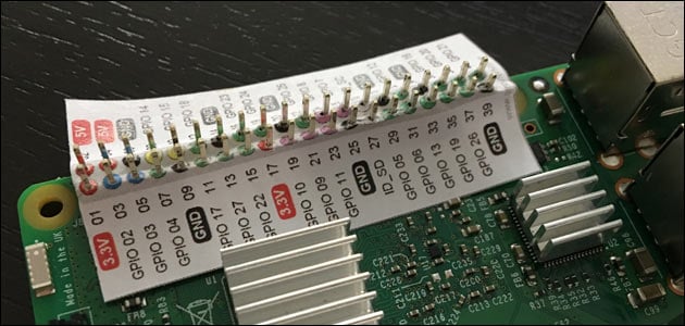
It is a actual sized and designed to pushed on the pins. Inlcuded in this article is a template custom labelled for this project.
Hook-Up Wires
It is easiest to use hookup wire that has one female end and one male end. The female end is easily pushed onto the RaspberryPI pins and the male end is easily inserted into the Breadboard.
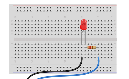
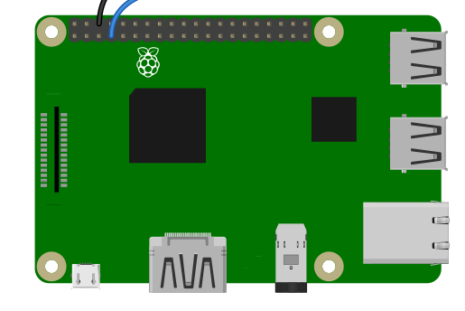
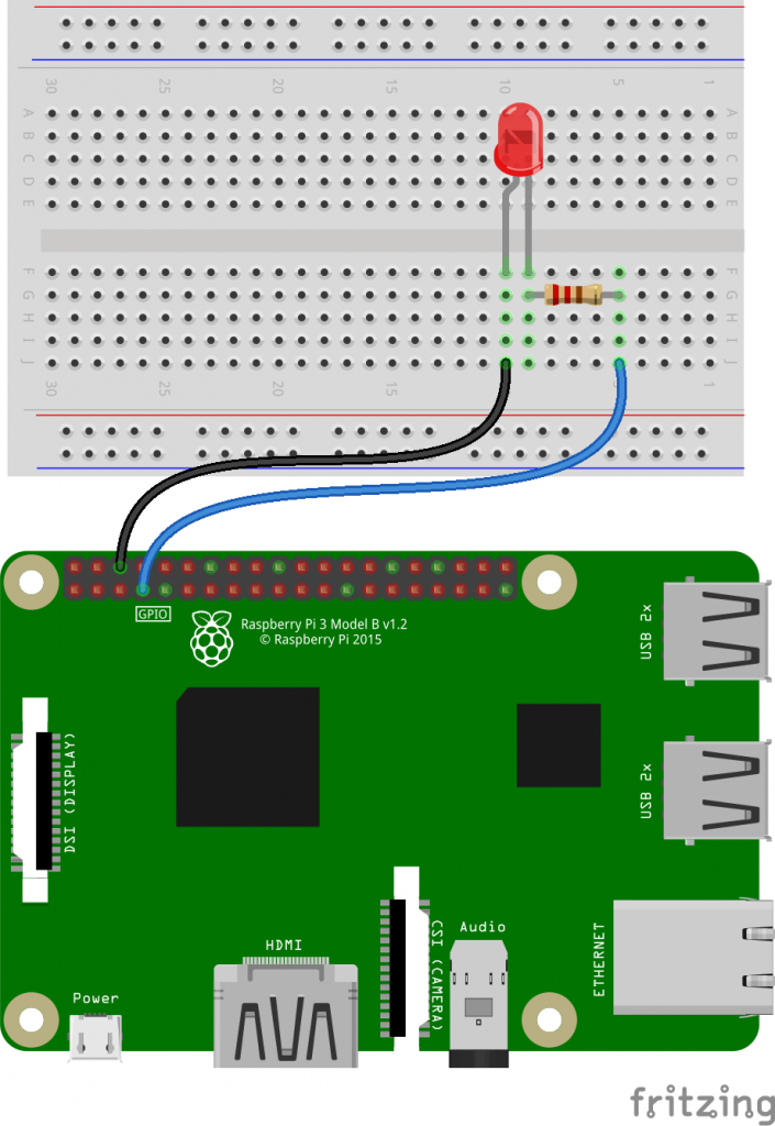
1.) Connect One hookup wire from Pin 6 GND on the Raspberry Pi to Column 10 on the Breadboard
2.) Connect One hookup wire from Pin 7 GPIO 4 on the Raspberry Pi to Column 5 on the Breadboard
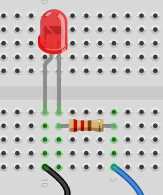
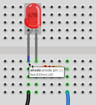
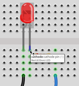
3. )Place the LED with the Short Lead, the Anode, inserted into Column 10 and the Long Lead, the Cathode into Column 9 on the Breadboard.
Identify LED Parts
- The Anode of the LED can be identified in three ways.
- It is the Long LEAD/Wire
- The Lens will be rounded ( flattened side is cathode )
- Looking into the led, the Anode is the “Post” the smaller metal bit.
- The Cathode of the LED can also be identified in three ways.
- It is the Short Lead/Wire
- The Lens will have ( usually ) a small flat spot.
- Inside the Lens the wire connects to the “Anvil” or the larger metal piece.
- Place the resistor from Column 9 to Column 6 on the Breadboard. The resistor has no polarity, so it can be connected in either direction.
That’s all it takes to hook up the LED.
The resistor is a used to limit the amount of current that goes through the LED, it protects the LED from ever getting to much current and burning out.
To aide with wiring here is a diagram from Fritzing:
Now Let’s Add Code
Log on to your Pi using the Pi Desktop or using SSH to get to a Terminal.
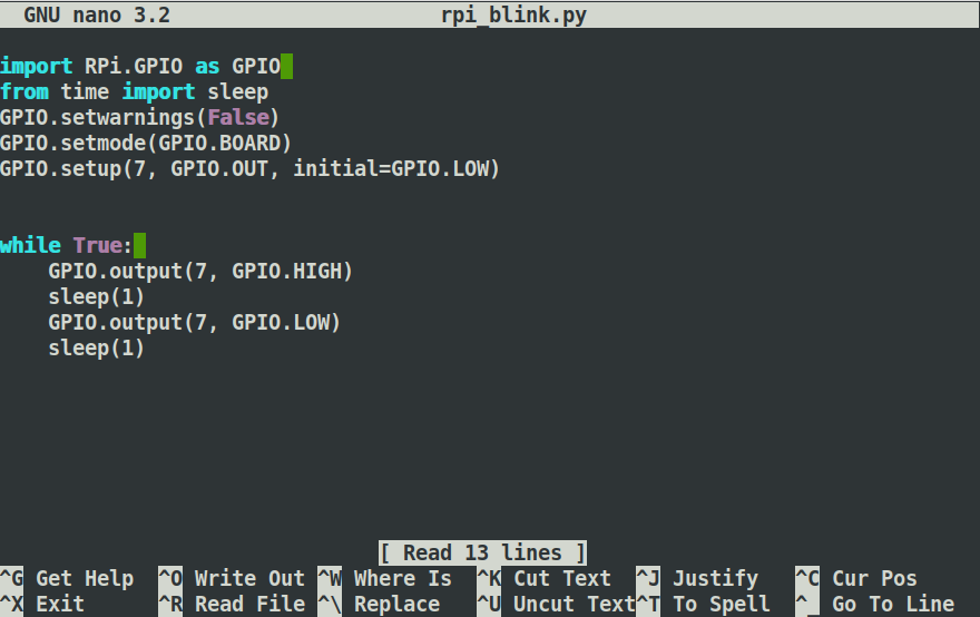
Place the following code into a file named rpi_blink.py ( or whatever name you like ), you just copy this code into your text editor or open your text editor and type it in.
import RPi.GPIO as GPIO
from time import sleep
GPIO.setwarnings(False)
GPIO.setmode(GPIO.BOARD)
GPIO.setup(7, GPIO.OUT, initial=GPIO.LOW)


while True:
    GPIO.output(7, GPIO.HIGH)
    sleep(1)
    GPIO.output(7, GPIO.LOW)
    sleep(1)
Once you svae the code you can execute the project as follows:
python rpi_blink.py
To stop the code from running press
ctrl-c
Additional Activities
Blink Faster or Slower
To make the LED blink faster you can experiment with different values within the Sleep( ) command.
Try changing the value in Sleep to .1, it should look like this
while True:
    GPIO.output(7, GPIO.HIGH)
    sleep(.1)
    GPIO.output(7, GPIO.LOW)
    sleep(.1)
Make sure you change it in both locations/
Blink at different rates
To make the LED stay on for a different amount of time than it stays off change the values in sleep to differnent values.
A quick blink, can look like this:
while True:
    GPIO.output(7, GPIO.HIGH)
    sleep(.1)
    GPIO.output(7, GPIO.LOW)
    sleep(1)
It will blink for one tenth of a second then stay off for a full second.
When working with electronics this approach can be used to signal different states.
Experiment with different values to see what you can come up with.